


15km 30km 80km 150km long-distance wireless video transmitter receiver transmission transceiver PA 2W 5W 10W


15km 30km long-distance wireless video transmitter receiver transmission transceiver
15km 30km 80km 150km long-distance wireless video transmitter-receiver transmission transceiver

Table of Contents
Selling Points / Features / Advantage


Signal Strength
Receiver screen can show the signal strength of the transmitter, users can move better reception place.

Video + Data + Control
Except for video, it also supports two-way transfer of data and control commands via the UART between the transmitter and the receiver.

Lower Latency
From the receiver’s computer screen snap, we can see the current transmission latency /delay is 28-76ms (millisecond). details

Bandwidth Presettable
The transmission bandwidth can be presentable at 3M, 5M, 10M, and 20M. Details 10-15-20Mbps
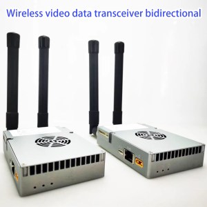
Two Antenna on the TX RX Transceiver
ANT1 for transceiver mode, ANT2 for receiving mode

Full set in the package
The package is including transmitter, receiver, both side antenna and accessories cable. Picture

- Based on OFDM technology, a Web camera (HD camera with ethernet) is recommended.
- Two-way broadband wireless link equipment (The receiver can get the audio-video download, it also can upload the data to the receiver)
- Interface: 2X Ethernet ports, 3X RS232 serial ports, audio input-output (More control operation) If your camera is HDMI output, then it needs an extra encoder device, which can encode the HDMI video and audio signal to digital data to this transmitter. At the receiver, it can connect your computer or NVR directly, if you need the output to an HDMI monitor, then it also needs an extra decoder device to encode the digital data to HDMI video and audio signal.
- Default Data Interface is RS232, We also can modify it to TTL, Sbus, or RS485, please contact us if you need to know how to connect it to your flight controller, for example, Pix hawk 4.
- Data Port Baud Rate: Data Port 1 supports 1200, 2400, 4800, 9600, 19200, 38400, 57600, 115200, 230400, 460800; Data Port 2 and Data Port 3 support 1200, 2400, 4800, 9600, 19200, 38400, 57600, 115200.
- Dual antennas: The SMA connector ANT1 main antenna works in transceiver mode, ANT2 auxiliary antenna works in receive mode.
- Wireless working frequency band: 1427.9~1447.9MHz (1.4G) or 806~826MHz (800Mhz), or optional 2401.5~2481.5MHz (2.4G) support automatic frequency hopping in the frequency band (default working frequency is 1.4G)
- Wireless bandwidth: 3MHz, 5MHz, 10MHz, 20MHz, all nodes share the working bandwidth, and the maximum sharing rate of the system is 30Mbps.
- Modulation mode: QPSK/QAM16/QAM64 automatic adaptation.
- Networking mode: point-to-point, point-to-multi-point star network. (For example, 6 cameras and a transmitter to one receiver.)
- Wireless transmitting power: 10W.
- The node receiving sensitivity: -103 at 10MHz bandwidth.
- Support AES128 encryption and decryption.
- Transmission distance: 15km/30km/80km/150km optional.
- The device configuration and wireless working status can be viewed through the Web UI of the network port or the serial port.
- 2W PA: DC12~16V, 33dBm, the average power consumption of the video transmitter is less than 12W, and the average power consumption of the video receiver is less than 10W. (Yellow power connector is XT30PW / XT60PW) (Without Any external PA, the module has 300mW, 25dBm)
5W PA: DC24~25V, 37dBm, the average power consumption of the video transmitter is less than 22W, and the average power consumption of the video receiver is less than 16W.
10W PA: DC24~30V, 40-41dBm, 28V power supply is recommended, the maximum average power consumption is less than 1.4A@28V, and the instantaneous peak power supply requirement can reach 2.8A@28V. - Size: 124*67.8*28.5mm (excluding the connector extending out of the shell, etc.).
- Weight: 0.3W 133 grams, 2W 142 grams, 5W 142grams, 10W 242.5 grams

Input Output
| I/O | Description |
| Ethernet 1 | 4PIN ZH1.5mm connector bridged with Ethernet2 |
| Ethernet 2 | RJ45 connector bridged with Ethernet1 |
| RS232*3 | 9PIN ZH1.5mm connector, 3 channel RS232 uart |
| Audio in/out | 4PIN ZH1.5mm connector, audio in and audio out port |
| Power in | XT30PW-M connector |
| ANT1 | TX/RX Antenna port, SMA female |
| ANT2 | Rx Antenna port, SMA female |
| Power LED | The red light on normally powered |
| Node LED | Blue light for Node type indicator |
| Link LED | Green light, wireless link working status indicator |

Transmitting Method


see Web UI configuration details

2W 27km Test transmitter and receiver map

FAQs
1. What battery should I prepare for this 10W Power Amplifier transceiver?
The power supply of this transmitter and battery both are 3A@28V. At the normal time, the battery we used for tested is 7AH, it can work for 2~4 hours. If you buy15AH chargeable battery, it can work continuously for about 4~8 hours.
2. Regarding the video transmitter, what are the frequencies available? Could we choose 2.4 GHz as an option or does it have to be 1.4GHz or 800MHz?
There is three frequencies to choose from 800Mhz, 1.4G, and 2.4G.
But there is no 10W Power Amplifier for 150km at 2.4Ghz. So if the buyer want to support 150km transmission distance, only 800Mhz and 1.2G can be chosen.
Not only switch the frequency at the web UI parameter easily, after changing the frequency, it also needs to change the Power Amplifier inside and the same frequency transmitter and receiver antenna. So buyer should confirm which frequency you need before delivery. The antenna is customized according to this frequency.

3. Can I use one 3-meter RF cable from the transmitter to the antenna?
Regarding the RF cable, our engineer doesn't recommend that you used it so long. There will be a reduced 0.5dB for one meter RF cable. For 3 meters RF cable, the signal strength will be reduced by 1.5dB.
In order to support long-distance, It is better that you use the RF cable less than 1 meter?
In fact, the transmitter is very smaller, it is better to keep a short distance from the transmitter to the transmitter antenna. The power supply cable for the transmitter and ethernet cable from the camera to the transmitter can be longer as there are no losses like RF cable.
4. It seems to support IP camera, but my video source or camera is HDMI or SDI video output, How can I use this transmitter and receiver?
Yes, the default video input is IP RJ45 ethernet port, if your camera is HDMI or SDI or AHD, just plus one small encoder box to solve this problem. Please check the below model.

5. Should I choose 800 Mhz or 1.4G for better reception? Has 1.4G interfered with the GPS antenna?
- If your area has a DVB-T or DVB-T2 digital television signal, the TV frequency range is 170-860Mhz, it has including 800Mhz, so choose 1.4G is better.
- Because the GPS antenna receives the GPS signal and the GPS direction on the drone is up, our transmitter antenna is pointing down to send the signal to the ground. As a result, the 1.4G frequency effect on GPS is negligible.
6. How about the package of one set? Gross weight and size?
The package size is 125 x 23 x 11cm. Gross Weight:3.72KG, Volume Weight:7.5KG

Here is the full set picture.

7. Should I set the frequency hopping as yes on the parameter setting?
Regarding frequency hopping, the engineer has some suggestions for you.

- As the system frequency range is 20Mb, if your bandwidth is chosen 20Mb, then it can not hop (only one point). If the bandwidth is chosen 10Mb, then you have two points to hop, if the bandwidth is chosen 5Mb, then you have 4 points to hop.
- If 1410Mhz has jammed, then 1420Mhz also has jammed, as the frequency is too close.
- When hopping frequency, the data or video transmission will be disconnected, and your video will be frozen.
- At the normal time, it is better to choose hopping is NOT.
- If your transmission distance is less than 15~22km, then we have another option to choose from, the frequency has 110Mb, and even if you choose 20Mb bandwidth, it has 5 points to choose from for frequency hopping.
8. Does this model support multi-transmitters cameras to one single receiver? For example, use 3 IP cameras at 1 video transmitter.

multi-camera transmitter and receiver for ptz surveillance camera
Yes, it supports.
There are two solutions for the multi-transmitter cameras to one signal receiver.
Please check the below test video at youtube
1. 4 IP cameras -> Net Hub -> Transmitter <===> Receiver -> Computer Screen
2. 4 IP cameras -> NVR HDMI output -> HDMI encoder IP output -> Transmitter <===> Receiver -> computer screen.
9. Does your two-ways wireless video data audio link module support sbus for inav?

Mini-SBUS-Conversion-Module-Uart-to-Sbus-Sbus-to-Uart-TTL-RS232
If you need to support S.bus, then please tell us before shippment, and we will modify our RS232 to TTL.
Our TX900 has three RS232 ports. If you need it to support S.bus, just need plus one small converter from S.BUS to RS232 is ok. ( Mini SBUS Conversion Module Uart to Sbus, Sbus to Uart ).

Please tell us if you need sbus port before delivery. Our engineer will modify the D2 port from RS232 to Sbus.

10. How can we get the RSSI, SNR quickly, go to debug session, without login to the web; Do you have AT commands to arquire this information?
RSSI wireless link status data requires customers (such as flight controllers) to manually send AT commands to obtain it. It can be obtained in two ways:
- Configure UART3 (data port 3rd) as an AT command serial port, and then send AT commands through UART3 (D3) to obtain. https://ivcan.com/change-d3-from-transparent-serial-port-to-at-command/
- Update the firmware version 1.5.1 or above, so that there will be an additional TCP server inside for customers to access through TCP to send AT commands to obtain the wireless status.
- The LED light is used to indicate the wireless connection status (for example, if the wireless link is disconnected, the light will go out), and there is no dedicated external pin to notify the customer flight control.
Or see the UART AT command list here.
or see https://ivcan.com/how-to-get-the-rssi-and-snr-on-the-drone-transmitter/
11. Do these air modules give the failsafe command to the flight controller When is a connection between air and ground modules lost?
- The serial port of our wireless video transmission is transparent, and no data is actively sent to the flight controller. This is controlled by the ground station.
- It won't send the failsafe command, but you can see the link status light from the signal indicator.

- Here is the link status signal strength indicator means
- Not Bright: Indicates that the wireless link of the module is not connected
- Red: Indicates that the wireless link of the module has been connected, but the wireless signal strength is very weak
- Orange: Indicates that the wireless link of the module has been connected, and the wireless signal strength is medium
- Green: Indicates that the wireless link of the module has been connected, and the wireless signal strength is very strong
- We understand that you hope to have this function, If aircraft loses signal during flight it will not return to home because flight controller will not understand that rc link is lost.
- You need to see the link status LED light, if it is Orange or Red, you should control the plane back in advance.
- You also can get the RSSI at the below windows

12. How to upgrade the latest firmware of the wireless video transmitter and receiver
Please check the upgrade firmware setps, download the latest upgrade firmware at the below link.
https://ivcan.com/how-to-upgrade-the-latest-firmware-of-the-wireless-video-transmitter-and-receiver
13. Is your system is capable for using 3 nodes? As we have to use 3rd nodes as the repeater in the center between the transmitter and receiver.
At the normal usage, one node as the transmitter, another node as the receiver. If you need to support long range or over a mountain top, like the below picture, yes, please buy 3rd nord as the reapter.
You just need to put the 3rd node in the middle and set the 3rd node be a 2D3U then ok.

How to set 3rd node be 2D3U?
Set with AT command:
at+cfun=0
at^dstc=0
at+cfun=1
Restart the link device after the operation


14. How to distinguish module 15km from 30km by software and appearance look?
On the Web UI parameter mangagment page and debug section,
AT command
Input AT^DGMR?
If you get result is 6602, then it is 15km version.
If you get result is 6603, then it is 30km version.

15. Does your wireless video transmitter support 4K video?
4K video is supported.
4K video stream generally has more than 8Mbps, and 1080P video generally has more than 2M, so the distance of our wireless video transmission when transmitting 4K video will be shorter than that of 1080P.
In one word, the higher the definition of the video, the shorter the transmission distance.
The video compression is smaller, and the transmission distance is supported farther.
16. When sending a video signal, if a packet is lost during transit, does the receiver notice and ask the transmitter to send the lost packet again package?
In the process of video transmission, if there is data loss, the picture will appear mosaic or stagnation, freeze and other phenomena.
There will be a limited number of retransmissions at the wireless link level (of course, data errors will also occur if the situation is not good). The upper-layer application on the end will not be aware of it, nor will it ask the sender to retransmit.
If the signal of the wireless link is not good at a certain point after the distance is extended, and there are always bit errors, it is impossible to design it to be retransmitted all the time, so that the end user experience will be very poor.
The wireless link layer has a limited retransmission mechanism. We have tested the tcp protocol for transmission at the video transmission layer (trying to retransmit on the upper layer through the tcp protocol), but the test found that there is no obvious improvement, and it will also lead to uncontrollable delays.
17. What should I do if the transmitter is very hot?
- The heat generated by the aircraft side is much larger than that of the ground side. If the fan is running, check whether the air inlet and outlet of the lower fan (the positions of the heat sinks at both ends) are blocked
- Try changing the power supply of the air unit transmitter from 24V to 12~18V (the transmit power will be reduced to about 35~36DB)
- Slightly reduce the transmit power of the aircraft by the below AT commands: AT^DSSMTP="23" Reboot after setting
Question: Are these settings maximum power of the module? (24 dBm)
Answer: 24dBm is the maximum output power of the link Module, and the gain of the PA (about 14dBm) needs to be added. The actual transmission power after the 24V power supply PA output is about 38dBm.
18. Would you fill out the below form to show us more information?
|
# |
Procurement Specifications |
YesNo |
Notes |
|
1 |
The unit shall operate in the VHF BAND and UHF band with its RF transmissions. |
UHF |
1427.9-1467.9Mhz |
|
2 |
The unit shall have an RF output power of 27 dBm or more. |
Yes |
2W 33dBm 5W 37dBm 10W 40-41dBm |
|
3 |
The unit shall provide Serial (Bidirectional, Fullduplex) as data interface. (RS232 or RS422) |
Yes |
RS232 bidirectional full duplex |
|
4 |
The unit power consumption shall not exceed 25W. |
Yes |
<22W |
|
5 |
The unit mass shall not exceed 250 grams.
|
Yes |
<150 grams (142grams) |
|
6 |
The unit shall have a data rate of at least 4.8 Kbps |
Yes |
RS232:>50kBps Ethernet:>2M Bps |
Lead time: 10 days for small quantity order.
HS code: 8517629900
19. Is it possible to use the ground unit for the air unit and vice versa with a change in the setting?
The difference between the air unit (transmitter) and ground unit (receiver) is two points:
One is the device type: Air unit (transmitter) is the access node and the ground unit (receiver) is the central node.
Two is the rate ratio of the downlink and up link. Over 30km, the best rate ratio is 4:1 or 3:2.
20. What happens when I plug the receiver 192.168.1.12 to the LAN port of an existing router 10.220.20.1?
If you don't want to connect the receiver ethernet cable directly to the computer. Then it is not easy to access the receiver at your local network.
Here is two solutions for you.
1. Add the IP address of the 192.168.1.x network segment on the PC side (the PC can be configured with multiple network segment IP addresses)
2. Modify the IP of the wireless video data receiver from 192.168.1.12 to the address of the 10.220.20.x network segment to meet your local network.
For further questions and solutions, please talk with your local area network workmate or engineer, our receiver is like a computer with IP address, it should keep the network segment IP address at the same, for example, 192.168.1.xxx.
21. The base of the receiving antenna is a large magnetic sucker base. Can you replace it with a U-shaped clamp bracket?

Yes, we can change the receiver antenna with a U-shaped clamp bracket to replace the magnetic sucker base.
It is easy to fix on the pole. And magnetic items are charged extra during shipping.
22. If I use two drones, one is a transmitter, another is a repeater, and they are controlled by one receiver. Does TX900 support to control of the mission plane and relay drone?
- Yes, there are three solutions to do that.
- TX900 has three data ports. Distinguish through different transparent serial ports, such as D2 to control relay aircraft and D3 to control mission aircraft. The disadvantage is that the TX900 receiver needs to be connected to two serial ports to send instructions separately.
- Use the same transparent serial port to send data in bulk, and then add layer protocols (such as header information) to the data to distinguish which aircraft should receive and process the data. The disadvantage is that the processing of sending and receiving data is complicated.
- Or use two receivers: One receiver is for the mission plane (transmitter), and another receiver is for the repeater drone. The connection and operation are easier.
Latest Test video from mountaintop to 27 km away to the seaside to check the long-range effect and operate at the receiver
Optional TX900B for some clients need frequency hopping function.
- TX900B-2W supports the frequency range is 1420~1530MHz, and there is 110Mb bandwidth to use. (800Mhz frequency range does not support this 110Mb bandwidth)
- The customer can set the working bandwidth as 1.4M/3M/5M/10M/20MHz (However 1.4M/3MHz may not be suited for video transmitting). Then TX900B-2W can work in FHSS mode (Frequency-hopping spread spectrum) and the central working frequency will be automatically selected by the system and may do frequency hopping (between 1420~1530MHz) during its working.
- Customers can also plan to use the frequency channels in the whole 1420~1530MHz and set the device to work in the fixed frequency channels too.
- TX900B-2W supports the longest distance at 22km.
- Except for the frequency range supported and the longest distance, the physical appearance, interface, UI, operation, and so on, the TX900B-2W is the same as the existing TX900B-15km-2W.
- TX900B-2W only supports a frequency range is 1420~1530MHz, it does not support 800MHz and 2.4GHz frequency ranges.
- There are two versions, TX900B-2W-15km, and TX900B-2W-22km.
- As the TX900B-2W frequency range is 110Mb, so if you configure the working bandwidth as 10Mb, then you will get 11 points to hopping.
- TX900B supports 110Mb bandwidth for frequency hopping and only has three transmission ranges optional, 22km, 55km, and 150km.
Download
| 1 | D3 serial port function configuration |
| 2 | TX900 transparent transmission and UDP serial port instructions |
Related products


Video Transmitter
H264 Wireless Video HDMI Image Transmission 10-100km COFDM Transmitter NLOS composite video SDI
$999.00

HDMI to IP Encoder
$399.00

Video Transmitter
$699.00 – $824.00


Video Transmitter
2300Mhz 2.4G Long Range UAV Video Data Transmission System For Drone VTOL Multicopter
$0.00
Latest test video for the drone Long-range Wirless Video Transmitter and Receiver
2W PA 27KM Real Test from mountain top to seaside Line-of-Sight
Latest 110km test video for the drone Long-range Wirless Video Transmitter and Receiver
NLOS wireless video transmitter and receiver test video in building indoor lift non line of sight
65 KM drone UAV Really fly Test Wireless Video Transmission
65 KM drone UAV Really fly Test Wireless Video Transmission
1.5km for ground NLOS, 10-20-30km LOS air to ground wireless video transmitter receiver transmission
COFDM-912T NLOS (non-line of sight) 1.5km real test in city, buildings, trees and roads
Web Device Management UI for UAV wireless video data link transmitter transmission by IP Net camera
Cheapest CVBS RCA 720P Wireless Video Transmitter + 1080P Receiver Support 128 encryption
COFDM-912T Really test in the complex city environment, transmitter in the car, receiver in the building
Cheap Wireless video transmitter and receiver's small screen has great help on signal strength lock
OFDM Wireless Video Transmitter for IP Cameras Lightweight Long Range Transmission Automatic Network
Transmission Distance
Flight Control Protocol
Transmitter Video Input
Wireless Transmit Method
Obstacle and Sight
Encrypt and decrypt
Transmission Carrier
Data Direction
Antenna
FAQs about Wireless Video Transmitter and Receiver
1. What types of video inputs port does your wireless video transmitter have?
Our wireless video transmitters have these types of video input interfaces: HDMI 1080P and 4K HDMI, CVBS composite, SDI, AHD, IP Ethernet, BNC, or tell us what type do you need, our engineer will modify to meet your demand.
2. What is the transmission distance supported by your wireless video transmitter?
Our transmission distance can be adjusted by adding power amplifiers. At present, the main ones are 15km, 30km, 50km, 80km, 100km , and 150km, which depend on the needs of customers.
Of course, the transmission distances listed above are all within LOS the line-of-sight range. If there are obstacles between the transmitter and the receiver, NLOS (the non-line-of-sight), the transmission distance is greatly reduced, only 1km or 2km, depending on the number of intermediate obstacles and the local wireless environment.
3. What is one-way or two-way? Simples vs half-duplex, full-duplex
One-way means, We can only transmit and download video or data from the wireless video transmitter to the receiver in one direction, and we cannot upload video or data from the receiver to the transmitter. This type is also called simplex.
Two-way means that, not only we can download video or data from our wireless transmitter to the receiver, but also we can upload the video or data from the receiver to the transmitter. This is very suitable for operating drones. You can not only see the real-time video transmitted from the drone, but also upload the command to control the drone or the command to control the PTZ camera to adjust the angle to the transmitter. This can operate simultaneously. This type also named half-dulpex or full-duplex.
Please check the details at the below link. https://ivcan.com/request-a-quote-of-wireless-video-transmission/#simplex
4. Does your HDMI video transmitter support encryption and receiver decryption?
Most Wireless video transmitters now support AES128 or AES256 bit encryption and decryption, depending on which model you choose. Please contact us to verify.
5. Can the frequency of the wireless video transmitter be modified after ordinary users receive the goods?
The frequencies of both the wireless video transmitter and the wireless video receiver can be modified. Users need to purchase additional parameter configuration boards.
However, considering that the corresponding power amplifier and antenna are already fixed within a certain range when the goods are sent out. If the user adjusts the frequency of the transmitter, the corresponding power amplifier, transmitter antenna and receiver antenna should also be modified to the same frequency, and these users need to be prepared. If not, it will cause the frequency of the wireless video transmitter to be different from the frequency of the antenna, making reception difficult. So please be sure to inform the correct frequency you need before placing an order.
If it is for security or confidentiality, you can use the encryption and decryption functions of the transmitter and receiver, which can ensure that your video transmission is private. .
6. I saw that your model is very similar to my needs, but I need to modify one of the parameters, is that possible?
Yes, all our product parameters can be customized according to customer's needs. If you have a special request, please let us know via the link below.
https://ivcan.com/request-a-quote-of-wireless-video-transmission/
7. What should I do if my wireless video receiver shows a weak signal?
- Change the place of the receiver to avoid potential local interference from strong magnetic environments.
- Ensure that the antennas on both the transmitter and receiver are vertical.
- Please raise the antennas of the transmitter and receiver to maintain a certain height difference.
- Please look around to ensure that there are no obstacles between the transmitter and receiver.
- Change the orientation of the receiver antenna.
- If it doesn't work, try moving the receiver to be near the transmitter's position to see if it exceeds the effective wireless transmission distance.
- Or consider adding a relay of the transmitting between the transmitter and receiver.
- The antenna should be as high off the ground as possible, as the ground will absorb the transmitted signal.
8. Can I buy modules of the transmitters and amplifiers only? I want to assemble them into my equipment.
We can, of course, supply wireless video transmitter modules and power amplifiers.
For the first sample test, I recommend that you purchase the entire set of products because our engineers have optimized the parameters to achieve the best performance.
After you have completed your test verification, you can remove the case or heat sink, install it in your device, and constantly adjust the parameters to achieve the best performance. In the future, you will be able to purchase only the modules or accessories that you require.
9. Can you take a test video for me to see before shipping?
Of course, we also understand that wireless video transmission transmitters and receivers are very expensive. You are far away from the China factory. and hope that the goods you receive are fit for the best performance.
If you pay special attention to a specific parameter or function, we can take some test videos based on the features you want to see, please feel free to contact us. It won't be shipped to you directly without your approval.
10. How to test the latency of wireless video transmitters and receivers?
To test the delay of the wireless video transmitter and receiver, we need to do two tests.
The first is to test the delay from the camera to the display.
The second is the camera, plus the display plus the wireless image transmission transmitter and the delay of the receiver.
Subtracting the two test results is the real delay of the wireless video transmitter and receiver.
As a professional long-range HDMI wireless video transmitter and receiver supplier and manufacturer in China Shenzhen, we produce the best wireless video transmitter and receiver for many years, and we got a good reputation and best reviews.
Some famous brands of wireless video transmitters, like Blackmagic, Holyland mars 300 400s, Accsoon cine eye 5g, RavenEye, Zhiyun, Inkee benbox, actiontec, CVW SWIFT 800, dahua, iogear, Artek pat-225k, microlite, nyrius, teradek.
The best budget wireless broadcast video transmitter and the receiver have many applications, for 4K tv, CCTV security camera, vehicle backup camera, PTZ video camera kit, battery-powered, computer, sony camcorder, wifi video conference system, CANON DSLR, UAV drone, pc computer laptop, projector, in-car, iPhone iPad, live streaming, GoPro sports camera, raspberry pi, Xbox.
The full HD video, audio, data link smallest 1080P wireless video transmitter and the receiver has many input and output connectors, like AV composite CVBS, HDMI, SDI, BNC, VGA, USB.
The wireless video transmitter sender TX RX frequency has 170-806Mhz, 1.2ghz, 2.4G, 5.8G, lowest but not zero latency. In order to support longer distances, the power amplifier has 10w, 20watts, and even 30W.
What is a best buy FHD wireless video transmitter at a cheap price? It should consider your details requirement, choose suitably, not expensive, if you have any doubt, please fulfil the request a quote form, our engineer will offer you a solution.

Latest 2W Power Amplifier 27 KM long-range wireless video transmitter receiver living demo image data link transmission in 2022
In order to better show our customers the actual support distance and use the effect of the 2W PA 30km long-distance image transmission transmitter and receiver, we conducted an actual test recently and found a Meisha Peak, from here to the seaside of Nan’ao, The distance is 27 kilometers. This [...]
Read More
06
Feb
Feb

New long-range wireless video transmitter and receiver for drone camera 110km 10W PA wireless video data audio link real test
110km test video of the long-range wireless video transmitter and receiver for the drone video camera Why do we want to do this 110km long-range test this time? Some clients ask me the longest distance of the wireless video transmitter and receiver, now we recommended this 10W Power Amplifier model, [...]
Read More
07
Oct
Oct

Latest Wireless Video Data Audio Transmitter and Receiver Test Video in 2022
Wireless Video Data Audio Transmitter and Receiver TX900 2 Watts 27km test video from mountain top to the seaside. (Video inside) Wireless Video Data Audio Transmitter and Receiver, Two-way, Download-Upload A customer saw our real test video about the 2 watts Power Amplifier 27km long-range wireless video transmitter and receiver. He [...]
Read More
01
Sep
Sep

60-80 km wireless video transmitter receiver transmission really flying test
Really a drone flying test of 60-80 km wireless video transmitter receiver transmission This is a video transmitter and receiver for drone UAV cameras, the best in 2023, and it has many satisfied reviews. It also supports ground to ground, if you have any project that needs a video transmitter [...]
Read More
24
Oct
Oct