


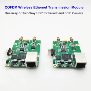
10W PA 150KM airborne video data link long-range UAV
10W PA 150km airborne video data link long-range UAV wireless transmission transmitter-receiver broadband
tactical handhold

Table of Contents
Selling Points / Features / Advantage


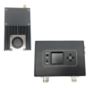
Signal Strength
Receiver screen can show the signal strength of the transmitter, users can move better reception place.

Video + Data + Control
Bidirectional transmission, Video Data Telemetry Downlink from Drone to GCS, Flight Control Commands Uplink from GCS to Drone

Lower Latency
From the receiver’s computer screen snap, we can see the current transmission latency delay is 28-76ms (millisecond). details

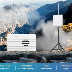
Bandwidth Presettable
The transmission bandwidth can be presentable at 3M, 5M, 10M, and 20M. Details 10-15-20Mbps
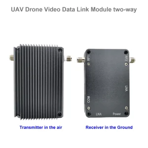
Two Antenna on the TX RX Transceiver
ANT1 for transceiver mode, ANT2 for receiving mode

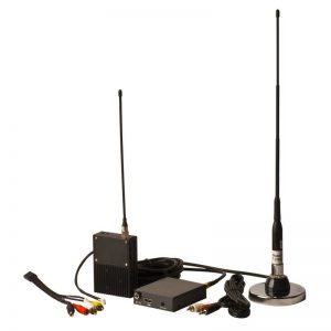
Full set in the package
The package is including transmitter, receiver, both side antenna and accessories cable. Picture
Recommended
- TDD OFDM full-duplex wireless transceiver for video and data Link
- Up to 30Mbps Iperf Throughput @20MHz channel
- Supports Point-to-Point and Point-to-Multipoint Networks
- Interface through a web browser or control uart
- 2 Ethernet and 3 channel RS232 data link
- Audio in/out supported by inside Audio codec
- Long-range wireless transceiver with 10W RF power
This model was designed for video and data wireless transmission with a two-way wireless data link. This OFDM radio device works at 800MHz or 1.4GHz bands, with frequency hopping technology (FHSS) to ensure better stability signal communication.

Features
- TDD OFDM modulation
- Supports 806~826HMz band or 1428~1448MHz band
- Supports FHSS inside each band
- 1.4/3/5/10/20MHz bandwidths
- Max 30Mbps@20MHz throughput
- RF transmission power: 10W
- Constellation: QPSK, 16QAM, 64QAM, self-adaption
- Sensitivity: -108dBm(1Mbps)
- Supports IP data transmission(2 Ethernet ports)
- Supports serial data transmission(3 channel, RS232)
- 1~15km(ground-to-ground), 30~150km(UAV-to-ground, optional distance grade)
- Web UI or Control UART for management
- AES128 encryption
- Uplink and downlink stream control
- Networking mode: Point-to-Point, Point-to-Multipoint, Relay, and Mesh(specify)
- Movement Speed: Supports no less than 120km/h
- Compact size and lightweight
- Rugged aluminum alloy housing
- Power input: 24~30V
- Power consumption<40W(RF Power 10W)
- Dimensions: 124*67.8*28.5mm
- Weight: 252g

Input / Output
| I/O | Description |
| Ethernet1 | 4pin ZH1.5mm connector, bridged with Ethernet2 |
| Ethernet2 | RJ45 connector, bridged with Ethernet1 |
| RS232*3 | 9pin ZH1.5mm connector, 3 channel RS232 uart |
| Audio in/out | 4pin ZH1.5mm connector, audio in and audio out port |
| Power-in | XT30PW-M connector |
| ANT1 | Tx/Rx Antenna port, SMA female |
| ANT2 | Rx Antenna port, SMA female |


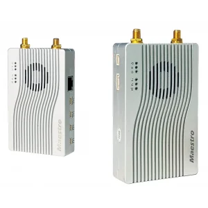
New metal design

- Cancel the audio interface
- The previous 9PIN (three serial ports) sockets have been replaced with 3X 3PIN sockets with locks, which makes the connection more reliable.
- Anti-rotation protection is added to the SMA antenna connector.
- Casing color changed from silver to gray.


FAQs
The power supply of this transmitter and battery both are 3A@28V. At the normal time, the battery we used for tested is 7AH, it can work for 2~4 hours. If you buy15AH chargeable battery, it can work continuously for about 4~8 hours.
Not only switch the frequency at the web UI parameter easily, after changing the frequency, it also needs to change the Power Amplifier inside and the same frequency transmitter and receiver antenna. So buyer should confirm which frequency you need before delivery. The antenna is customized according to this frequency.

Regarding the RF cable, our engineer doesn't recommend that you used it so long. There will be a reduced 0.5dB for one meter RF cable. For 3 meters RF cable, the signal strength will be reduced by 1.5dB.
In order to support long-distance, It is better that you use the RF cable less than 1 meter?
In fact, the transmitter is very smaller, it is better to keep a short distance from the transmitter to the transmitter antenna. The power supply cable for the transmitter and ethernet cable from the camera to the transmitter can be longer as there are no losses like RF cable.
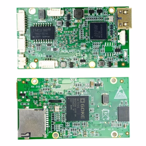
Yes, the default video input is IP RJ45 ethernet port, if your camera is HDMI or SDI or AHD, just plus one small encoder box to solve this problem. Please check the below model.

- If your area has a DVB-T or DVB-T2 digital television signal, the TV frequency range is 170-860Mhz, it has including 800Mhz, so choose 1.4G is better.
- Because the GPS antenna receives the GPS signal and the GPS direction on the drone is up, our transmitter antenna is pointing down to send the signal to the ground. As a result, the 1.4G frequency effect on GPS is negligible.
The package size is 125 x 23 x 11cm. Gross Weight:3.72KG, Volume Weight:7.5KG

Here is the full set picture.

Regarding frequency hopping, the engineer has some suggestions for you.

- As the system frequency range is 20Mb, if your bandwidth is chosen 20Mb, then it can not hop (only one point). If the bandwidth is chosen 10Mb, then you have two points to hop, if the bandwidth is chosen 5Mb, then you have 4 points to hop.
- If 1410Mhz has jammed, then 1420Mhz also has jammed, as the frequency is too close.
- When hopping frequency, the data or video transmission will be disconnected, and your video will be frozen.
- At the normal time, it is better to choose hopping is NOT.
- If your transmission distance is less than 15~22km, then we have another option to choose from, the frequency has 110Mb, and even if you choose 20Mb bandwidth, it has 5 points to choose from for frequency hopping.

If you need to support S.bus, then please tell us before shippment, and we will modify our RS232 to TTL.
Our TX900 has three RS232 ports. If you need it to support S.bus, just need plus one small converter from S.BUS to RS232 is ok. ( Mini SBUS Conversion Module Uart to Sbus, Sbus to Uart ).


Please tell us if you need sbus port before delivery. Our engineer will modify the D2 port from RS232 to Sbus.

RSSI wireless link status data requires customers (such as flight controllers) to manually send AT commands to obtain it. It can be obtained in two ways:
- Configure UART3 (data port 3rd) as an AT command serial port, and then send AT commands through UART3 (D3) to obtain. https://ivcan.com/change-d3-from-transparent-serial-port-to-at-command/
- Update the firmware version 1.5.1 or above, so that there will be an additional TCP server inside for customers to access through TCP to send AT commands to obtain the wireless status.
- The LED light is used to indicate the wireless connection status (for example, if the wireless link is disconnected, the light will go out), and there is no dedicated external pin to notify the customer flight control.
Or see the UART AT command list here.
or see https://ivcan.com/how-to-get-the-rssi-and-snr-on-the-drone-transmitter/
- The serial port of our wireless video transmission is transparent, and no data is actively sent to the flight controller. This is controlled by the ground station.
- It won't send the failsafe command, but you can see the link status light from the signal indicator.

- Here is the link status signal strength indicator means
- Not Bright: Indicates that the wireless link of the module is not connected
- Red: Indicates that the wireless link of the module has been connected, but the wireless signal strength is very weak
- Orange: Indicates that the wireless link of the module has been connected, and the wireless signal strength is medium
- Green: Indicates that the wireless link of the module has been connected, and the wireless signal strength is very strong
- We understand that you hope to have this function, If aircraft loses signal during flight it will not return to home because flight controller will not understand that rc link is lost.
- You need to see the link status LED light, if it is Orange or Red, you should control the plane back in advance.
- You also can get the RSSI at the below windows


Please check the upgrade firmware setps, download the latest upgrade firmware at the below link.
https://ivcan.com/how-to-upgrade-the-latest-firmware-of-the-wireless-video-transmitter-and-receiver
At the normal usage, one node as the transmitter, another node as the receiver. If you need to support long range or over a mountain top, like the below picture, yes, please buy 3rd nord as the reapter.
You just need to put the 3rd node in the middle and set the 3rd node be a 2D3U then ok.

How to set 3rd node be 2D3U?
Set with AT command:
at+cfun=0
at^dstc=0
at+cfun=1
Restart the link device after the operation


On the Web UI parameter mangagment page and debug section,
AT command
Input AT^DGMR?
If you get result is 6602, then it is 15km version.
If you get result is 6603, then it is 30km version.

4K video is supported.
4K video stream generally has more than 8Mbps, and 1080P video generally has more than 2M, so the distance of our wireless video transmission when transmitting 4K video will be shorter than that of 1080P.
In one word, the higher the definition of the video, the shorter the transmission distance.
The video compression is smaller, and the transmission distance is supported farther.
In the process of video transmission, if there is data loss, the picture will appear mosaic or stagnation, freeze and other phenomena.
There will be a limited number of retransmissions at the wireless link level (of course, data errors will also occur if the situation is not good). The upper-layer application on the end will not be aware of it, nor will it ask the sender to retransmit.
If the signal of the wireless link is not good at a certain point after the distance is extended, and there are always bit errors, it is impossible to design it to be retransmitted all the time, so that the end user experience will be very poor.
The wireless link layer has a limited retransmission mechanism. We have tested the tcp protocol for transmission at the video transmission layer (trying to retransmit on the upper layer through the tcp protocol), but the test found that there is no obvious improvement, and it will also lead to uncontrollable delays.
- The heat generated by the aircraft side is much larger than that of the ground side. If the fan is running, check whether the air inlet and outlet of the lower fan (the positions of the heat sinks at both ends) are blocked
- Try changing the power supply of the air unit transmitter from 24V to 12~18V (the transmit power will be reduced to about 35~36DB)
- Slightly reduce the transmit power of the aircraft by the below AT commands: AT^DSSMTP="23" Reboot after setting
Question: Are these settings maximum power of the module? (24 dBm)
Answer: 24dBm is the maximum output power of the link Module, and the gain of the PA (about 14dBm) needs to be added. The actual transmission power after the 24V power supply PA output is about 38dBm.
|
# |
Procurement Specifications |
YesNo |
Notes |
|
1 |
The unit shall operate in the VHF BAND and UHF band with its RF transmissions. |
UHF |
1427.9-1467.9Mhz |
|
2 |
The unit shall have an RF output power of 27 dBm or more. |
Yes |
2W 33dBm 5W 37dBm 10W 40-41dBm |
|
3 |
The unit shall provide Serial (Bidirectional, Fullduplex) as data interface. (RS232 or RS422) |
Yes |
RS232 bidirectional full duplex |
|
4 |
The unit power consumption shall not exceed 25W. |
Yes |
<22W |
|
5 |
The unit mass shall not exceed 250 grams.
|
Yes |
<150 grams (142grams) |
|
6 |
The unit shall have a data rate of at least 4.8 Kbps |
Yes |
RS232:>50kBps Ethernet:>2M Bps |
Lead time: 10 days for small quantity order.
HS code: 8517629900
The difference between the air unit (transmitter) and ground unit (receiver) is two points:
One is the device type: Air unit (transmitter) is the access node and the ground unit (receiver) is the central node.
Two is the rate ratio of the downlink and up link. Over 30km, the best rate ratio is 4:1 or 3:2.
If you don't want to connect the receiver ethernet cable directly to the computer. Then it is not easy to access the receiver at your local network.
Here is two solutions for you.
1. Add the IP address of the 192.168.1.x network segment on the PC side (the PC can be configured with multiple network segment IP addresses)
2. Modify the IP of the wireless video data receiver from 192.168.1.12 to the address of the 10.220.20.x network segment to meet your local network.
For further questions and solutions, please talk with your local area network workmate or engineer, our receiver is like a computer with IP address, it should keep the network segment IP address at the same, for example, 192.168.1.xxx.

- Yes, there are three solutions to do that.
- TX900 has three data ports. Distinguish through different transparent serial ports, such as D2 to control relay aircraft and D3 to control mission aircraft. The disadvantage is that the TX900 receiver needs to be connected to two serial ports to send instructions separately.
- Use the same transparent serial port to send data in bulk, and then add layer protocols (such as header information) to the data to distinguish which aircraft should receive and process the data. The disadvantage is that the processing of sending and receiving data is complicated.
- Or use two receivers: One receiver is for the mission plane (transmitter), and another receiver is for the repeater drone. The connection and operation are easier.
Transmitting network Method
It supports two operating modes: Access Node and Central Node. It can be managed through web UI or Control uart.
It supports features of a maximum of 16 Access Nodes connected to a Central Node.
All of the Nodes are in the same wireless LAN and share the whole transmission bandwidth (maximum 30Mbps@20MHz throughput).
For data from the Central Node to the Access Node, we call downlink, and for data from the Access Node to the Central Node, we call uplink. Uplink and downlink stream ratio can be controlled through web UI or Control uart.
When using it for Point-to-Point transmitting, uplink and downlink share the whole transmission bandwidth (maximum 30Mbps@20MHz throughput) too.
It supports networking modes: Point-to-Point, Point-to-Multipoint, Relay, and Mesh (specify mesh version when ordered).
Web Device Management UI


Latest Test video from mountaintop to 27 km away to the seaside to check the long-range effect and operate at the receiver


Relative Post


Bruno Bomfim –
This powerful 10W PA system, utilizing military-grade AES-128 encryption, provides remarkably clear video and telemetry transmission across distances exceeding 150 kilometers. Rigorous testing in both mountainous terrain and heavily congested urban environments revealed zero signal drops, demonstrating exceptional performance in challenging conditions. This technology will revolutionize border surveillance and the capabilities of combat UAVs, marking a significant turning point in both fields.