


UAV drone video data link module wireless video transmitter and receiver for camera two-way long-range TDD transceiver lightweight

Table of Contents
UAV drone video data link Advantage
- Small in size 7.2X4.8X1cm, lightweight (less than 60 grams), 2X5-watt PA dimension
- long-range. The omnidirectional fiberglass antenna can reach 30 km. The directional antenna can reach 50KM
- At the same time, it has 2 bidirectional RS232 serial ports, which are convenient for uploading and uploading data. (RS232 only, can not do TTL)
- The minimum delay can reach 28ms (not including the camera recording and monitor displaying time)
- 20ms excluding monitor and camera. 1080P 60 about 80ms
- Using TDD-OFDM transmission protocol, long-range, a large amount of data, free networking, stable and durable.
- Using wide temperature components, it can work normally from -40 degrees to 85 degrees
- IP67 protection can be used in harsh outdoor environments for a long time.
- Compared with ordinary bridges, the distance is 10 times that of ordinary WIFI transmission protocols.
- Multiple power supply redundancy designs, high reliability.
- They are specifically optimized for video streaming.

Application
- Main purpose: Cooperate with IP cameras to transmit video data over long-range.
- Security monitoring: such as agricultural monitoring, industrial monitoring, factory warehouse monitoring, water monitoring, forest fire prevention, mountain monitoring, etc.
- Internet of Things: Ad hoc network data transmission.
- UAV Drones: imagery, data transmission.
- Special industry: power station, water conservancy, etc.
- Public security and armed police firefighting: miniaturized image transmission can be customized. For example, multiple ad hoc network cameras.

Specification
- Working Frequency: Default 1.4G (1407-1497MHz) or 2.3G (2310-2380Mhz)band
- Built-in 2 * 1W Power Amplifier
- Power Supply: 7-18V
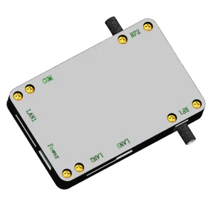
Connector Input Output

Define:
If the light is not on, it means that the wireless video data transmission has a problem, maybe the working power is too small, or the power amplifier is damaged.
| signal strength | LED P2 | LED P3 | LED P4 |
| > -70 | always | always | always |
| -71 to -75 | always | always | -75 |
| -75 to -80 | off | always | always |
| -80 to -83 | on | -80 | and |
| -83 to -88 | always | off | off |
| less than -88 | flash | off | off |
| no signal | marquee |
5, Data Serial Port, 1.25mm connector, 232 level. (some motherboards only have serial port 1, no serial port 2)
| serial number | Function |
| 1 | GND |
| 2 | 5V output |
| 3 | Serial 2 RX |
| 4 | Serial 2 TX |
| 5 | Serial 1 RX |
| 6 | Serial 1 TX |
6, 26Pin LNA 0.5mm FPC flexible cable connector, defined as follows:
| serial number | function | note |
| 1 | 5V | Output |
| 2 | 5V | output |
| 3 | NC | |
| 4 | RF1 | RF1 Switch |
| 5 | RF2 | RF2 Switch |
| 6 | ANTD | Antenna Switch |
| 7 | NC | |
| 8 | NC | |
| 9 | RESET | MESH firmware reset |
| 10 | LNA2_LED | |
| 11 | LNA1_LED | |
| 12 | GND | |
| 13 | 12V | 12V input |
| 14 | 12V | 12V input |
| 15 | GND | |
| 16 | RSSI_H | Received Signal Strength Indicator: Strong |
| 17 | RSSI_M | Received Signal Strength Indicator: Medium |
| 18 | RSSI_L | Received Signal Strength Indicator: Weak |
| 19 | ANTC | Antenna Switch on/off |
| 20 | PA1 | Power Amplifier 1 Switch |
| 21 | ANT1 | Antenna 1 Switch |
| 22 | LAN1_TX_N | Network Port |
| 23 | LNA1_TX_P | Network Port |
| 24 | GND | |
| 25 | LNA1_RX_N | Network Port |
| 26 | LNA1_RX_P | Network Port |
7, Power Input: 7-18V, the positive and negative poles are prohibited to be reversed! Otherwise, it will be damaged
Please directly weld the wire or weld the XT30 connector. The connector is also marked with positive and negative poles, don’t reverse it!
8, Onboard Pin Network Port:
Pin spacing 1.27mm, 4PIN (This network port can only configure the data of the local device and the other party, and cannot access the data of LAN6 and LAN9)

9, 20PIN 0.5mm FPC flexible cable connector, the definition is as follows: (provided later)
10, LAN port:
1.25mm connector, If it is often plugged and unplugged, it is recommended to externally connect the RJ45 socket with an isolation transformer.
- LAN-RX-P
- LAN-RX-N
- LAN-TX-P
- LAN-TX-N


11, LAN port: 12PIN interface, PCI-E, and USB interface


12, Fan Interface: GND is ground, 5V outputs 5V, VCC is connected to the main power supply, and the connector is 78172 series
13, Jumper switch:
1. Turn it to the ON position to turn off the RF1 amplifier power.
2. Turn it to the ON position and turn off the power of the RF2 amplifier.
3, not used.
4. Restore the factory settings.
After powering on and entering the system, dial the code to 1 for more than 5 seconds, and then dial the code to 0 to restore the factory settings.


Parameter Configuration Tool for Windows Software Download
FAQs
Yes, this wireless video data link module supports point and one-point to multi-points. Considering the bandwidth and transmission speed, our engineer suggests connecting up to four points at the same time.
Thanks.
I will take a test video to show you the exact ways and real latency of the two-way wireless video data audio link module.
1.4G has stock.
The engineer told me that he can modify the frequency from 1.4G to 2.3G (2310-2380Mhz), can not 2.4G now.
Question: Can you make it the working frequency at 2280-2380Mhz?
Sorry, no we don't have it at 2280-2380Mhz, only 2310-2380Mhz.
- Support RJ45 IP Ethernet (IP camera or computer)
- Support Rs-232 data port. (shell printed COM, 5, Data Serial Port, 1.25mm connector, 232 level.
- Support 10Mbps
- 2x1W PA support 10~30km
2x2w PA support 30~50km - 2x1W 7.2X4.8X1cm (72x48x10mm) less than 60 grams
- Only 1.4G now, not support 2.1G or 4.8G as working frequency.
- OK.Support as relay to extend long-range.
- The device between the transmitter and receiver needs to be configured as the master, and the other two as slaves.
Please check the below picture.


The Vcan1401 point-to-point model only outputs data via RS232. The product is too small to fit an RS232 to TTL converter.
If you must connect a TTL interface, you need to add an RS232 to TTL converter outside the machine.


iVcan.com –
This VCAN1401 TDD transceiver module is an absolute game-changer. The long-range capability is incredible – we confidently fly beyond visual line of sight for inspections and mapping, knowing the crucial video feed and telemetry will remain rock-solid. The two-way communication via TDD is seamless; there’s virtually zero noticeable lag between control inputs and the drone’s response, making complex maneuvers feel instinctive. Even in areas with typical RF clutter, the video transmission stays remarkably clear and stable. The reliability is outstanding – no more nervous moments flying ‘blind’ due to signal dropouts. Setup was straightforward, and the robust build quality inspires total confidence. This module delivers professional-grade, real-time awareness and control, unlocking the drone’s true potential. Worth every penny for serious pilots!
iVcan.com –
Very good