


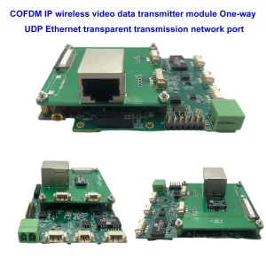
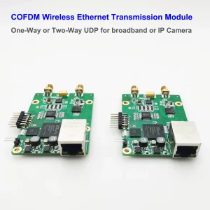
UAV Wireless Video Data RC Control Link
Two-way wireless transmission digital data video link module DLB

Table of Contents
Feature
- TDD OFDM two-way wireless video data RC control link module board
- Band 800Mhz / 1.4G / 2.4G: 806~826HMz, 1428~1448MHz, 2402~2482MHz
- Support FHSS FHSS Frequency-hopping spread spectrum automatic frequency hopping
- Bandwidth: 3MHz, 5MHz, 10MHz, 20MHz, selectable
- Max 30Mbps@20MHz bandwidth
- RF transmission power: 25±2 dBm
- Constellation: QPSK, 16QAM, 64QAM, self-adaption
- Sensitivity: -106dBm(2.4GHz 1Mbps), -108dBm(1.4GHz 1Mbps), -108dBm(800MHz 1Mbps)
- Supports transparent IP Data transmission(2 IP network ports)
- Supports serial data transmission(3 X RS232 UART or TTL)
- Supports audio input and output with codec on board
- Without installing an external Power Amplifier, Support upto 17km LOS (UAV-to-ground) and 2km LOS (ground-to-ground)
- Web UI or Serial UART for management
- AES128 encryption and decryption
- Uplink and downlink stream control
- Networking type communication: point-to-point, one point-to-many points, many points-to-one point, IP mesh networking (optional)
- Power consumption: <4.5W
- Dimensions: 58*64*13mm (CAD dimension file)
- Weight:32g
- Working Temp. -20℃ ~ +65℃
- Storage Temp. -40℃ ~ +80℃
- Dual antenna transmit and receive, MIMO mode of operation
- Modulation method: QPSK/QAM16/QAM64 automatic adaptation
- Maximum transmission power: 25±2dBm
- Support wireless link encryption and decryption
- Up to 16 access nodes can be connected to one central node.
Sensitivity
| Frequency Band | 2.4GHz(1Mbps) | 1.4GHz(1Mbps) | 800MHz(1mbps) |
| 20Mhz Bandwidth | -99dBm | / | / |
| 10Mhz Bandwidth | -102dBm | -103dBm | -103dBm |
| 5Mhz Bandwidth | -104dBm | -106dBm | -106dBm |
| 3Mhz Bandwidth | -106dBm | -108dBm | -108dBm |


Interface Defines
I/O signal
| Power in | XT30PW-M connector, DC in:7~30V |
| Ethernet1 | 4PIN ZH1.5mm connector |
| Ethernet2 | RJ45 connector |
| Data uart1 | 3PIN ZH1.5mm connector, TTL 3.3V |
| Data uart2 and uart3 | 6PIN PH1.25mm connector, uart3 works as control uart and data uart, TTL 3.3V |
| Audio input and output | 4PIN PH1.25mm connector |
| USB | Micro USB connector, for software upgrading |
| Switch | TX/Rx control signal for outside power amplifier |
| Main-Antenna | TX/Rx Antenna port, IPEX |
| Second-Antenna | Rx Antenna port, IPEX |
| 12V out | On-board 12V out(<150mA), for cool fan power supply |
| Power Led | Red, light on normal powered |
| Node Led | Blue, light on when the transceiver module works as a receiver node;
Blink when the transceiver module works as a transmitter node |
| Link Led | Light off – indicates that the node is not linked to the wireless network;
Red light – indicates that the node is linked, but the wireless signal is weak; Orange light – indicates that the node is linked, wireless signal is middle; Green light – indicates that the node is linked, the wireless signal is strong. |

Ethernet-1: two-way wireless transparent transmission network port, 4PIN 1.25mm pitch with a buckle carrier
RJ45 Ethernet-2: two-way wireless transparent transmission network port, 4PIN 1.25mm pitch carrier or direct 4PIN soldering hole
Data-UART: bidirectional transparent data serial port, TTL 3.3V level, 3PIN 1.25mm pitch with a snap carrier RS232-1/2/3
Antenna 1: main antenna interface, IPEX carrier
Antenna 2: Auxiliary antenna interface, IPEX carrier. The auxiliary antenna can only be received. When this wireless video link module is used for communication, it can be double-received or received.
Power: The power input interface, supports 7~24V wide voltage input, and maximum power consumption is less than 3.5W.
USB: 4PIN 1.25mm pitch carrier, not yet open to users.
Config UART: 4PIN 1.25mm pitch carrier, not yet open to users.
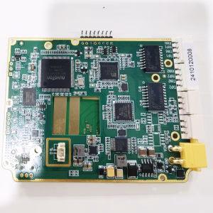
This UAV Wireless Video Data RC Control Link module measures 58x48mm (excluding the dimensions of the interface device extending from the edge of the board), the front device height is less than 3.2mm, the back device height is less than 4.5mm, the board thickness is 1.6mm, and the weight is 31.5g.
Power Supply
The power supply signal is shown in the figure above. The power input is 2 solder holes and supports 7~24V wide voltage input. 4V power supply is provided externally for the power supply of the cooling fan.
Ethernet and Data
Signal Indicator

Ethernet-1 light: Green, a signal indicator on the network port. The network port will flash when transmitting data normally.
RJ45 Ethernet-2 light: Green, network port two signal indicator, the network port will flash when transmitting data normally.
Power light: red, always on when power is normal
Signal strength light: The working status indicator of the wireless link. When the module works as a slave node, if the wireless connection with the master node is normal, the indicator will be on. This indicator is invalid when the module is working as the master node.
Audio Input/output define
Our UAV Wireless Video Data RC Control Link module supports the onboard audio codec. Customers can use these two-way audio/voice/speaker communication applications.
|
PIN |
Signal |
Description |
| Audio in | Line in by default(Specify Mic-in) | The audio will be sent to the target wireless remote module. |
| Audio out | Line out, drive earphones | When the node receives audio data from a remote wireless module, the audio will be played out on this PIN. |
| GND | GND | GND |
| Control | Software-defined | On/off switch control of audio input |
Specification
| Working frequency band | 1428~1448MHz or 802~826MHz |
| Channel bandwidth | 1.4MHz/3MHz/5MHz/10MHz/20MHz |
| Modulation method | QPSK/QAM16/QAM64 |
| Transmitting power | 300mW, 2W, 5W |
| Networking mode | point-to-point, point-to-multi-point star network |
| Transmission distance | air-to-ground 15km, 30km, 50km, 80km, 100km |
| Data interface | 2 network ports + 1 serial port |
| Wireless transmission rate | maximum 25Mbps, shared by all nodes in two-way transmission. |
| Antenna interface | 2 SMA connectors |
| Power supply | 7V~30V (recommended 12~28V) |
| Size | 102*52*21.5mm (PCBA only) |
| Weight | 127 grams |
FAQs
Yes, please check the blow video link at the youtube.
- This model support customizing the IP mesh function. There are three versions: 3km, 10km, and 50km according to build different the power amplifier.

- Normal default full duplex link module support relay, you should buy at least three or more units. One unit is the transmitter, one unit as the receiver, and the other unit can put the middle between the transmitter and receiver as the relay/repeater/extender.
The maximum RF transmission power of this two-way data video link module is 25±2 dBm, We also provides power amplifier to increase the RF Power to 2W/5W/10W. Below diagram shows how to add power amplifier outside of two-way digital data video link module.

Where is the IIC_SCL pin on the module?

Yes, Please check the below link product, which is used the wireless video data audio two-way link module to assemble, just plus the Power ampleifier and encloser and accessory.
TX900

There was no function to query the temperature of the module.
- Sure. It is ok.
- The Moningcore CX6600 (L1860C_P2P) is only an electronics module, you need to develop a peripheral circuit to support it, like power and ethernet and data Input Outport. And you also need to hire a software engineer to develop the firmware and UI for you.
- As a trial sample, it is better that you can buy our complete products to test. After you test and use them, the quality is satisfied, then try to buy the module or parts to develop it by yourself. You can copy our design and improve it to be an excellent product.
- After all, this is a radio transmission product, and any improper operation may interfere with the signal, resulting in shorter transmission distances.
- Sure. support.
- There is no optional frequency band of 2.4G modification on the web page, you need to send AT commands to modify or enter the Morningcore web page to modify.
- Sure. 58*64*13mm.
- If you need further dimension, please download our CAD file at the below link. (maybe you need AutoCAD or other CAD software to open it)
- https://ivcan.com/wp-content/uploads/2023/09/Vcan1681_dimmension.dxf
- Or check the below picture.

Question: Any recommendations on the PA + link module enclosure? Need an RF cavity filter? minimal box with cooling for the RF transistor?
- What range of the trail sample do you need?
We can offer you a 1~150 km range of the link module. You can add the PA later if you want. Min 15km and max 150km module cost is different. - The module can transfer the signal over 150km with the 10-watt PA to increase the signal. Without the PA, the transmission range is almost 10~15km.
- If you buy one 15km range module, even you plus the PA, the range is almost 15~17 km range. The signal strength and ability of the anti-interference will increase much.
- The Power consumption is about 4W.
- Current equals power consumption divided by supply voltage
- 4 / 12=0.33A, if you're on a 12-volt supply.
- There are two versions on the different frequency range.
-
1st version's frequency range is from 1420 Mhz to 1530 Mhz, with 110Mhz frequency width for FHSS.
-
2nd version's frequency range is from 806 Mhz to 826 Mhz or 1420 Mhz ~1530 MHz, with only 20Mhz or 40Mhz frequency width for FHSS.
-
Our engineer recommended that you choose 1st version, as it can supply more frequent points to choose from when the signal is weak or interfered with.
How to switch frequency of Drone Video Link from 800Mhz, 1.4G, 2.4G
More FAQ
long-range VTX video transmitter module
Wireless networking module
As a professional supplier of the TDD transceiver two-way digital data video link module circuit board factory in Shenzhen China, our TDD transceiver frequencies from 1428Mhz to 1448Mhz with the antenna. We also offer the TDD transceiver block diagram broadcasting code configuration and command datasheet tutorial user manual.
Our TDD transceiver design definition device has the driver for firmware and hardware. Our TDD transceiver IC module network systems have good quality best reviews. Especial model Vcan1681 and T17P, both can be IP mesh networking to meet your project demand. The IP mesh version has 3km, 10km, and 50km according to the built-in Power Amplifier.


Relative Post
- How to switch the roles of transmitter and receiver in the TDD module?
- What is your latest firmware?


Sophia Martinez –
The module’s compatibility with flight control systems like Pixhawk ensures seamless integration, facilitating transparent data transmission for UAV operations.