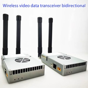
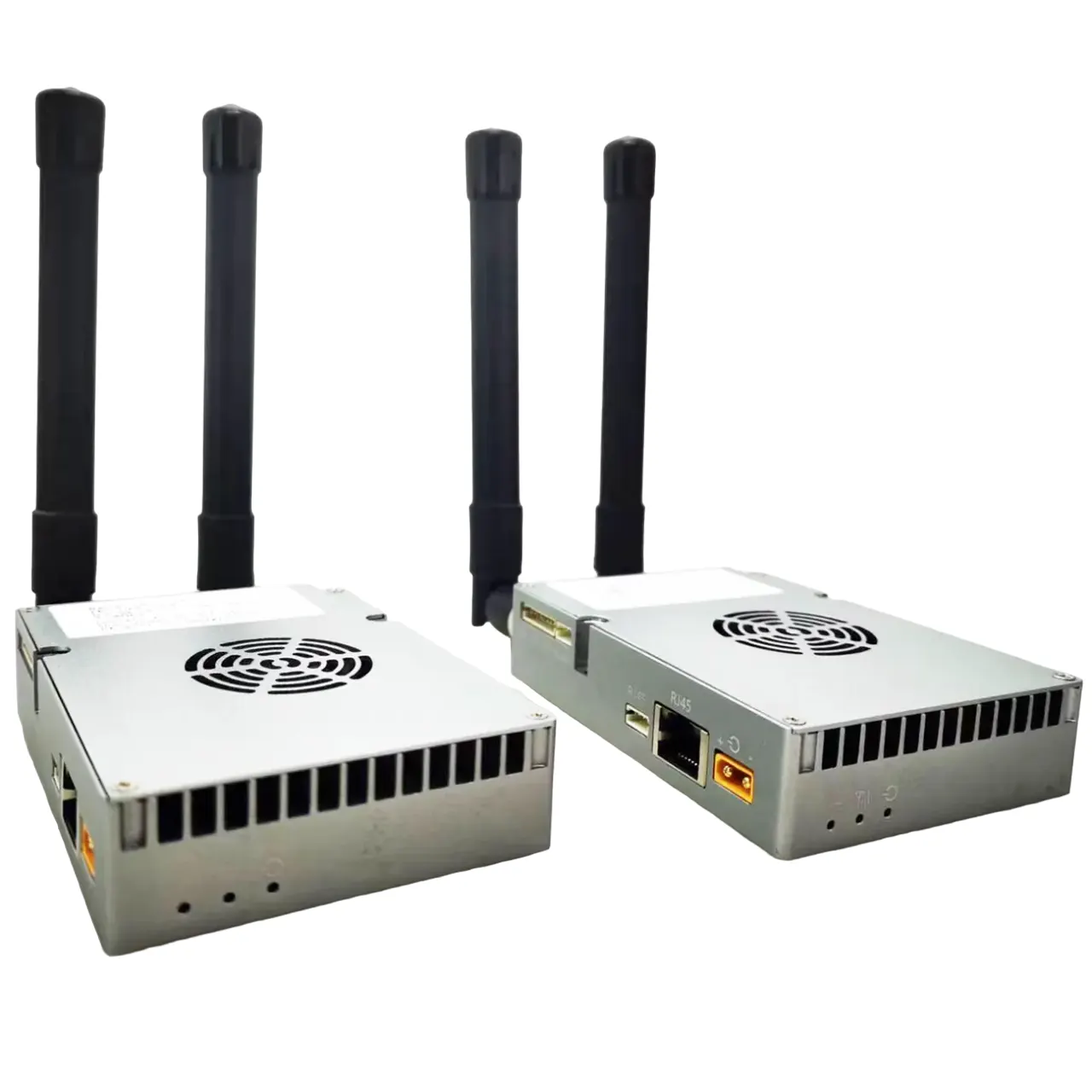
user manual for wireless video data transceiver TX900
Table of Contents
This user manual is suitable for the below models, TX900 and VCAN1681
-
 10W PA 150KM airborne video data link long-range UAV wireless transmission transmitter receiver broadband tactical handhold
 -
 15km 30km 80km 150km long-distance wireless video transmitter receiver transmission transceiver PA 2W 5W 10W
 -
 Two-way UAV Wireless Video Data RC Control Link module long-range bidirectional transceiver Transmitter-Receiver Vcan1681
About TX900 / VCAN1681 Module
The main module inside TX900 is the VCAN1681 transceiver module, so the software configuration operation is the same as the VCAN1681 module. This manual is based on the Star wireless network, The Mesh wireless network is similar and is only a few different from the Star wireless network.
About hardware and I/O signal, please view the product description of TX900 and VCAN1681.
For different applications, the parameters configuration of the wireless node (TX900 / VCAN1681, we will use wireless node to indicate TX900 and VCAN1681 below in this document) may be different. Normally, we have set up the wireless parameters ready-to-run according to customers’ applications before delivery. Customers need to pay close attention to the interface settings like uart, audio in and out, etc.
Bitrates and Node Setting
The star wireless network consists of one Central Node and several Access Nodes(maximum 16). All of the Nodes are in the same wireless network and share the whole transmission bandwidth (maximum 30Mbps @20MHz throughput). When the distance of the wireless nodes changes to larger, and the wireless signal is weaker, then the shared total bitrates will be smaller. Data from the Central Node to the Access Node, we call downlink, and data from the Access Node to the Central Node, we call uplink. Uplink and downlink stream ratio can be set through the web UI/AT command.

When using two nodes for video and control data transmission, it’s better to have large bitrates from the video transmitter side to the video receiver side, and little bitrates from the control data transmitter side to the receiver side. For drone application, we set the ground side as the central node and the drone side as the access node, and we need to transmit video from the drone to the ground, then we set the uplink and downlink stream ratio as 1D4U, which means the bitrates from drone to ground is four times to the bitrates from the ground to the drone. This is the principle for setting the uplink and downlink stream ratio.
Web UI
The wireless node can be managed via Web UI. The initial IP address is stamped on the device. Normally we set the IP address of the central node as 192.168.1.11, and the access node is 192.168.1.12 as default. And IP addresses for other access nodes are 192.168.1.13, 192.168.1.14, …, etc.
The URL of the web UI for each wireless node is its’ IP address, for example:
When you use the web browser to visit the web UI of the wireless node, please be sure the IP address of the connected computer is set as the same subnet as the node’s IP address, for example, 192.168.1.xxx. When you re-set any parameters in the web UI, the node should be rebooted to enable the change.
The IP address of your other device(IP camera, computer, etc..) on the two sides of the wireless nodes can be the same subnet of the nodes or can be a different subnet of the nodes. When you want the Ethernet devices on two sides of the wireless nodes to communicate through the wireless nodes, then the IP address on the two sides themselves should be in the same subnet.
Set uart parameters
The wireless node has 3 parts: uart1(D1), uart2(D2), uart3(D3). In the wireless connection, the uart1 of the local node is paired with the uart1 of all other nodes in the same star wireless network. uart2 of local node is paired with uart2 of speicified remote node, uart3 works as uart2. The protocol of uart1 is in the link layer, and the protocol of uart2 and uart3 are in the TCP layer. When you meet a problem with your current software systems communication through uart1, then you can change to uart2 or uart3.
The set baud rate for uart1 to mate with the upper system:

Data communication via uart1:

Set uart2 and uart3 parameters to mate with the upper system:

Data communication via uart2(or uart3) :
The data communication of uart2 and uart3 is different from uart1 because the protocol of uart2 and uart3 are in the TCP layer. The uart2 Tx data of the local node will be sent to uart2 of the specified “Remote IP” node(set on the web UI Serial page as shown in up picture).
When having several nodes in the wireless network, the uart2 Tx data of the local node can also be sent to uart2 of multicast nodes(set on the web UI Serial page as shown in the below picture).

Uart2 of other nodes who attend this Multicast 224.0.0.25 then will receive the uart2 data from it. Please view the below picture on how to set “attend Multicast 224.0.25” on the web UI of the Network page.
If the setting “Group IP” is 0.0.0.0, that means the node will not attend multicast, then this node will only receive uart2/uart3/audio data which was just sent to it. You can learn more about multicast by reading TCP/IP protocols technology documents too.
Uart3 works with the same principle of uart2 in data transmission mode.
To be noticed, Our wireless node only supports Multicast IP address in the scope of 224.0.0.23~224.0.0.255.
When the “Remote ip” of uart2 and uart3 and audio data is the same node IP(or Multicast IP), then you can also simply set it on the web UI of the Network page as shown below:
Set/View wireless parameters
We have already set wireless parameters ready to run according to customers’ applications before delivery. Customers can view it on the web UI.
Frequency:
Since TX900 is integrated with the VCAN1681 modem and power amplifier module together and the power amplifier is specified with the customers’ application, the frequency band can’t be changed.
Bandwidth:
When the bandwidth is larger, the wireless throughput(bitrates) will be higher, and the sensitivity will be lower. Our wireless node is self-adaption on the constellation and the throughput(bitrates) is also auto-changed based on the SNR, so we suggest setting bandwidth as 20MHz(maximum) to enable the possible largest wireless communication bitrates.
Tx Power:
This is to set the fixed RF power of the VCAN1681 modem, scope: [-40, 25] dBm. The RF power of TX900 is equal to this parameter plus the gain of the power amplifier. So, you may see it is set as 22 to 25 here for the TX900-2W node (24+11=35dBm, calculated deviation and channel loss, the final RF power is about 33dBm).
Slave Max Tx Power:
The central node will work in fixed RF power (parameter set in Tx Power). The RF power of the access node will be in self-adaption. Slave Max Tx Power is to set the maximum RF power of the node when it is in self-adaption. And also this parameter is just for the VCAN1681 modem itself. The RF power of TX900 is equal to this parameter plus the gain of the power amplifier.
View receiving status key parameters during node linking
Web UI 🡪 Debug 🡪click “Start”
The parameters will be shown as below picture:
Control node:
The reports are:
[19:38:22]: current time of the computerIP:12: receiving status from 192.168.1.12, the fourth segment of the IP address of the remote connecting node
ANT2 receiving status on antenna 1
ANT1 receiving status on antenna 2
RSSI: RSSI value
RSRP: RSRP value, maximum -44
Tx: local the VCAN1681 modem real-time transmitted RF power, again not plus the gain of power amplifier
SNR: real-time SNR value
Distance: The distance of the wireless signal from the remote node to the local node
Error_per: reports the percentage of error in the cycle
Error_per_total: reports the total error percentage after entering the connection state
Access node:
The reports of access nodes do not have “IP” since only one central node in the network. The reports of the central node should have “IP” since it may have several access nodes connected.
When the access node is near to central node, the RF signal is very strong, then you can see “Tx” is “-9” dBm here, because the RF power of the access node is in self-adaption.
Measure UDP bandwidth during node linking
The VCAN1681 system has built-in iperf3 tools and customers can measure udp bandwidth with it conveniently during node linking.
About iperf3 tools, please view https://iperf.fr/.
To measure udp bandwidth from one node(for example 192.168.1.12, we say it node12 below) to another node(for example 192.168.1.11, we say node11 below), run iperf server on node11(Web UI 🡪 Measure 🡪 Iperf Server 🡪 click “Run Server”) first, then run iperf3 client on node12(Web UI 🡪 Measure 🡪 Iperf Client 🡪set parameters 🡪 click “Run Client”).
Run AT Command via web UI
Customers can run AT Command to view/manage VCAN1681 modem parameters via web UI or uart3.
Web UI 🡪 Debug 🡪AT Command 🡪 Click “Send”
Run AT Command via uart3
Uart3(D3) of the wireless node is multiplexed as data uart and control uart. Normally uart3 works as data uart by default.
Web UI🡪 System page:
On the system page of the web UI, you can check the software version of your wireless node.
If the version number is larger than 1.4.1(including version 1.4.1), the uart3 of the wireless node works as data uart only(It’s not multiplexed as data uart and control uart).
If the version number is smaller than 1.4.1(not including version 1.4.1, for example, version 1.4), the uart3 of the wireless node is still multiplexed as data uart and control uart). For these versions, please follow the below description to switch uart3 to control mode.
Switch uart3 to control mode:
Step1: Connect uart3 of the wireless node with the upper system’s uart
Please notice, if the wireless node is TTL uart, then the upper system should also be TTL uart. If the wireless node is RS232 uart, then the upper system should also be RS232 uart.
Uart setting of the upper system: baud rate 115200, 8 data bits, 1 stop bits, no parity checking, no handshaking, text mode.
Step2: Send “+++<CR>” to the wireless node uart3
Start power on to the wireless node, the wireless node will complete system initialization in about 10 seconds. Then the node-LED in blue color will light up. After the node-LED lights up, the upper system sends “+++<CR>” to uart3 of the node(it should be operated in 1 minute, after 1 minute it will be invalid), and the node uart3 will feed back “Enter Config Mode!”, it means now uart3 switch to control mode.
<CR> means carriage return.
When uart3 works in control mode, you can run the AT command via uart3. For every AT command sent to uart3, you should have “<CR>” at the end of the command.
For example: AT^DRPS?<CR>
Switch uart3 back to data transmission mode:
When uart3 works in control mode, you can send “—<CR>” to uart3, then uart3 will feed back “Exit Config Mode!” to upper system uart. It means uart3 switches back to data transmission mode.
Typical examples of parameters setting via AT command
Example 1: set the uplink and downlink stream ratio
For the star wireless network node, it should set the uplink and downlink stream ratio on the central node:
AT+CFUN=0 //stop the modem
AT^DSTC=3 //set as Config3 (1D4U)
AT+CFUN=1 //Startup the modem
Notice: the wireless node version more than 20km distance level only supports config0 (2D3U) and Config3 (1D4U); The wireless node version less than 20km distance level supports config0 (2D3U), config1 (3D2U), Config2 (4D1U) and Config3 (1D4U).
Example 2: set the paired password
All of the nodes in the same wireless network should have the same password.
AT+CFUN=0
AT^DAPI=”AEF608AEF608AEF6″ //set the password as “AEF608AEF608AEF6”
AT+CFUN=1
Example 3: two pairs of wireless nodes work in the same area
Central node of the first pair wireless node:
AT+CFUN=0
AT^DAOCNDI=04 //04 means 1.4GHz band
AT^DAPI=”11223344″ //set the password as “11223344”
AT^DRPS=,2,”25″ //2 means 5MHz bandwidth, “25” means Tx rf power
AT^ddtc=1 //set as central node
AT^DFHC=0 //disable frequency hopping
AT^DLF=1,14304 //Lock the central working frequency as 1430.4MHz
AT^DSONSSF=2,1 //Disable sleep
AT^DSTC=3 //set the uplink and downlink stream ratio
It needs to reboot the node after setting it successfully.
Access node of the first pair wireless node:
AT+CFUN=0
AT^DAOCNDI=04
AT^DAPI=”11223344″
AT^DSSMTP=”25″ //set the maximum rf power of the access node
AT^ddtc=2 //set as access node
It needs to reboot the node after setting it successfully.
The central node of the second pair wireless node:
AT+CFUN=0
AT^DAOCNDI=04 //04 means 1.4GHz band
AT^DAPI=”678123″ //set the password as “678123”
AT^DRPS=,2,”25″ //2 means 5MHz bandwidth, “25” means Tx rf power
AT^ddtc=1 //set as central node
AT^DFHC=0 //disable frequency hopping
AT^DLF=1, 14453 //Lock the central working frequency as 1445.3MHz
AT^DSONSSF=2,1 //Disable sleep
AT^DSTC=3 //set the uplink and downlink stream ratio
It needs to reboot the node after setting it successfully.
The access node of the second pair wireless node:
AT+CFUN=0
AT^DAOCNDI=04
AT^DAPI=”678123″
AT^DSSMTP=”25″ //set the maximum RF power of the access node
AT^ddtc=2 //set as access node
It needs to reboot the node after setting it successfully.
Example 4: cancel the central working frequency lock
AT+CFUN=0
AT^DLF=0 // cancel the central working frequency lock
AT^DRPS=,5, //5 means 20MHz bandwidth
It needs to reboot the node after setting it successfully.
Example 5: set frequency band
AT+CFUN=0
AT^DSONSBR=65,8060,8259,66,14279,14478,64,24015,24814 //enable three band(800MHz/1400MHz/2400MHz)
AT^DAOCNDI=01 //set to work in 806~825.9MHz
It needs to reboot the node after setting it successfully.
AT+CFUN=0
AT^DSONSBR=65,8060,8259,66,14279,14478,64,24015,24814 //enable three band(800MHz/1400MHz/2400MHz)
AT^DAOCNDI=04 //set to work in 1427.9~1447.8MHz
It needs to reboot the node after setting it successfully.
AT+CFUN=0
AT^DSONSBR=65,8060,8259,66,14279,14478,64,24015,24814 //enable three band(800MHz/1400MHz/2400MHz)
AT^DAOCNDI=08 //set to work in 2401.5~2481.4MHz
It needs to reboot the node after setting it successfully.
AT+CFUN=0
AT^DSONSBR=65,8060,8259,66,14279,14478,64,24015,24814 //enable three band(800MHz/1400MHz/2400MHz)
AT^DAOCNDI=0D //set to work in 806~825.9MHz, 1427.9~1447.8MHz and 2401.5~2481.4MHz
It needs to reboot the node after setting it successfully.


