





Table of Contents
Version history
| Date | Version | Modification description |
| 20241020 | V1.0 | Initial version |
Notes
- Install the antenna before powering on the device to avoid circuit damage. Place the two antennas of the device at a distance greater than 15cm away from large metal structures to avoid communication obstruction caused by the preceding reasons.
- Make sure that other electronic devices are not placed too close to the antenna. To avoid affecting the ground noise of the device.
- Pull distance as far as possible to make the ground end antenna without obstacles. The height of the ground antenna is greater than 3 meters.
- Before use, please ensure that all the connections are tight and reliable, and all the components work normally.
- Please do not disassemble or modify, otherwise there will be no warranty. If the failure occurs during installation or testing. To solve the problem, please contact the original technical support.
1 Product overview
Vcan2149 is a miniaturized and self-developed TDD bidirectional graph integrated wireless transmission device. The product has the functions of real-time interference detection, adaptive frequency selection, adaptive stream, automatic retransmission and automatic power control, which greatly improves the ability of anti-multipath and anti-interference, and has the characteristics of high reliability, good stability and low delay.
This product is suitable for firefighting, inspection, monitoring, and other scenarios. In the case of good air-to-ground visibility, the transmission distance is up to 15KM+.
2 Product accessories
| Vcan2149 Product list (2) | |||
| No | Product | Instructions | Num |
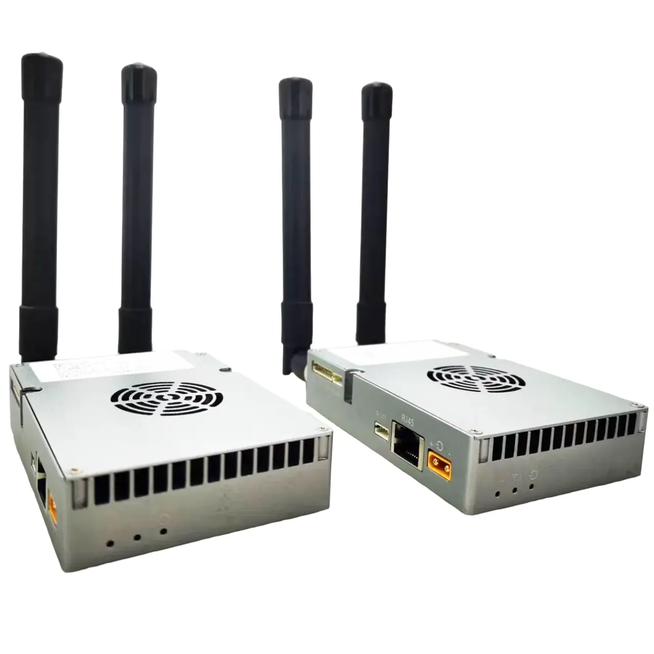
| 1 | Vcan2149 | TDD wireless transmission radio | 2 |
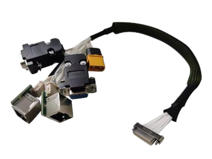
| 2 | J30J-15pin | 30cm cable | 2 |
| 3 | Little glue stick antenna | Gain: 2.5dBi | 2 |
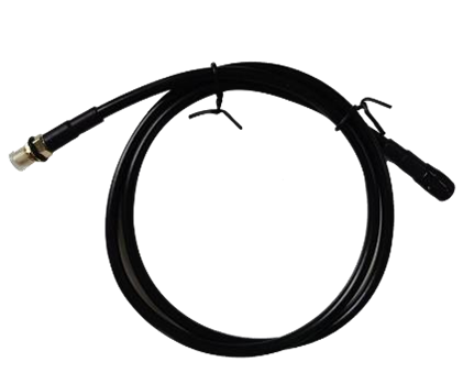
| 4 | Small antenna extension cable | 30cm cable | 2 |
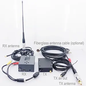
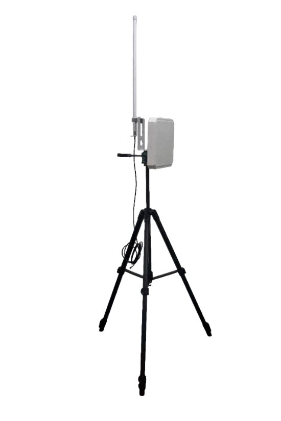
| 5 | All-in-one ground terminal antenna kit (optional) | 6dBi Omnidirectional antennas | 1 |
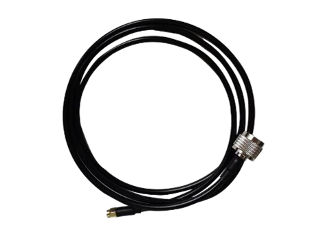
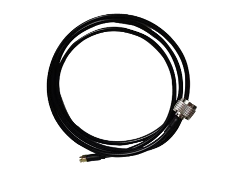
| 6 | Omnidirectional antenna 3m extension cable | 1 | |
| 7 | 3dBi flat directional antenna | 1 | |
| 8 | Directional antenna 4m extension cable | 1 | |
| 9 | 3m bracket + hand crank + U- shaped piece | 1 | |


3 Product connection
3.1 Connection diagram(Air)

3.2 Air Connection
Step1: Connect antenna
The distance between the two antennas must be greater than
15cm.The tail is connected to the J30J-15PIN.
Step2: Connect serial port
It can be connected to flight control equipment or other serial
devices. Note the serial port level.
Step3: Connect network port
A single or dual network port will be used to connect the camera.
Step4: Connect power
Power the equipment DC9~26V, typical value: +12V.
Step5: STS light
When the secondary terminal is powered on but not
synchronized, the STS displays a blue blinking indicator. When
the connection to the main terminal is normal, the STS light
displays evergreen/yellow/red based on the signal quality
strength.
3.3 Connection diagram(Ground)
3.4 Ground Connection
Step1: Connect antenna
The distance between the two antennas must be greater than
15cm.The tail is connected to the J30J-15PIN.
Step2: Connect serial port
It can be connected to the computer serial port tool or other serial port devices.
Step3: Connect network port
Connect the network to the computer, configure the IP address of the computer
to be in the same network segment as the IP address of the device. Then use the WEB or host computer for parameter configuration and status query
Step4: Connect power
Power the equipment DC9~26V, typical value: +12V.
Step5: STS light
When the primary device is powered on but not synchronized,
the STS displays a steady blue indicator. When the connection to the slave is normal, the STS light displays evergreen/yellow/red depending on the signal quality strength.
Step6: Play video
Open the video player software. View live transmission video.
4 Product use
4.1 Power supply
The device uses DC 9~26V power supply, the typical value is +12V@3A. Under different voltages, the average current of the master and slave terminals working normally is shown in the following table. Slave power consumption ≤25W, master power consumption ≤10W
| Supply voltage | Air(slave) Working current (A) | Ground(master) Working current (A) |
| 12V | 1.80A | 0.80A |
| 24V | 0.90A | 0.40A |
| 26V | 0.75A | 0.37A |
| Remark:It is recommended that customers use the 12V@3A power supply for power supply. | ||
4.2 Wiring definition

The interface of the Vcan2149 device adopts J30J-15PIN, and the default interface consists of 1 power supply, 1 network port, 1 RS232, 1 TTL, or 2 SBUS.
| Linear order | Pin name | Interface definition | Interface description | Signal direction |
| 1 | VCC | Power DC 9~26V | Power positive | I |
| 2 | VCC | Power positive | I | |
| 3 | GND | Power Negative | I | |
| 4 | GND | Power Negative | I | |
| 5 | TX1P+ | Ethernet port *1 | TX+ | O |
| 6 | TX1M- | TX- | O | |
| 7 | RX1P+ | RX+ | I | |
| 8 | RX1M- | RX- | I | |
| 9 | 5V | 5V Output | SBUS 5V Output | O |
| 10 | TXD_A | Serial port 1 RS232/TTL | Serial port 1 TX | O |
| 11 | RXD_A | Serial port 1 RX | I | |
| 12 | SBUS /TXD_B | Serial port 2 SBUS/TTL/RS232 (note 4,5) | SBUS Output (air) SBUS Input (ground) | IO |
| 13 | SBUS /RXD-B | IO | ||
| 14 | GND | Serial port 2 ground | O | |
| 15 | GND | Ground | Serial port 1 ground | O |
Note 1: Signal direction I indicates radio signal input and direction O indicates radio signal output.
Note 2: Serial port 1 can be used only with RS232/TTL, PIN10,11,15. The factory is determined by the hardware, the default is RS232.
Note 3: Serial port 2 can be used as RS232/TTL/SBUS. The factory is determined by hardware. TTL and SBUS can be switched by software.
Note 4: When serial port 2 is SBUS, SBUS12 and 13pin of the ground end are in, and SBUS12 and 13pin of the sky end are out.
Note 5: If dual SBuses are used, set the sky SBUS to Line12->Line12. line13->line13.
4.3 Product indicator meaning

Power light PWR(green)
When the PWR light is on, the device is powered on. Network port LAN (green)
The network port light blinks when data is being sent or received.
Status light STS (Four-color light)
Different colored lights indicate the current signal quality strength.
| The STS light represents the SNR size of the received signal | |
| STS colour | SNR |
| Blue | No connection is established |
| green | SNR>10dBm |
| yellow | 6dBm<SNR<10dBm |
| red | SNR<6dBm |
| Module | Mode | PWR led | LAN led | STS led |
| Master | unsynchronized | The green light is steady on | Data is being transmitted and blinking | The blue light is steady on |
| Master | synchronization | The green light is steady on | Data is being transmitted and blinking | (green/yellow/red) Proportional to the strength of the received signal |
| Slave | unsynchronized | The green light is steady on | Data is being transmitted and blinking | Blue light flashing |
| Slave | synchronization | The green light is steady on | Data is being transmitted and blinking | (green/yellow/red) Proportional to the strength of the received signal |
When the primary and secondary devices are not synchronized, the power PWR indicator of the primary and secondary devices is steady on, and the STS blue indicator of the primary device is always on. The blue light from the device’s STS flashes. When the master and slave are synchronized, the master and slave’s STS light becomes a three-color light, and the green light is displayed if the signal quality is good. A yellow light indicates moderate communication quality. A red light indicates poor communication quality. When the network port is sending or receiving data, the LAN indicators of the primary and secondary devices blink.
5 WEB Parameter configuration
5.1 Device IP
The default IP address of the master (ground) device is 192.168.10.250, the default IP address of the trunk device is 192.168.10.251, and the default IP address of the slave (airborne) device is 192.168.10.252. The alternate IP addresses are 192.192.192.192. The default IP address is the one that can be used and modified by the user. The alternate IP, 192.192.192.192, cannot be modified. If you forget the IP address, you can use the standby IP address to log in to the WEB page for parameter query and configuration.
⚫ Configure the network segment of the PC(192.168.10.xxx)
Open computer network connection and right-click properties. Open the TCP/IPv4 properties as shown in the following figure. Click Advanced, add IP, computer IP can add multiple IP at the same time. The same computer can work in different network segments. For example, add IP address 192.168.10.123 and IP address 192.168.1.123 at the same time. Complete the PC IP configuration and click OK to save the configuration.

5.2 WEB Account number and password
The default WEB address of the primary (ground unit) device is 192.168.10.250. The default Web input is 192.168.10.251 on the trunk (relay unit)device and 192.168.10.252 on the secondary (air unit) device.
Account: admin; Password: 123456

5.3 System Settings
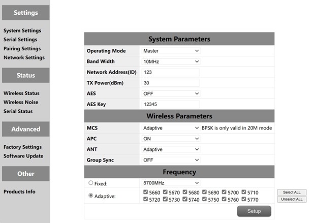
| No. | Function | Instructions |
| 1 | Operation mode | Configure the device as the master or slave end |
| 2 | Band Width | Channel bandwidth: 10/20MHz |
| 3 | Network ID | Network ID number: The same ID number is used for the same group. |
| 4 | TX Power(dBm) | Up to 30dBm |
| 5 | AES | AES Encryption switch |
| 6 | AES Key | AES Secret key |
| 7 | MCS | Automatic stream control (optional adaptive mode or fixed mode) |
| 8 | APC | Automatic power control (optional on or off) |
| 9 | ANT | Automatic selection of two antennas (fixed antenna 1 or antenna 2) |
| 10 | Multiple sets coexist | Multiple sets of coexisting switches enable multiple sets of devices to be used simultaneously |
| 11 | Frequency | Automatic frequency selection (optional adaptive or fixed) |
Multiple sets of coexistence: When the switch is turned on, a maximum of six pairs of devices can work at the same time, but they need to be used at a fixed frequency. Frequency selection: Fixed frequency or adaptive frequency can be selected. The adaptive frequency points can be selected all, or you can select any of the frequency points to use.
5.4 Serial Settings
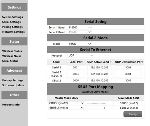
The Vcan2149 device has two serial ports, among which the level of serial ports 1 and 2 is RS232 or TTL level. The level of serial port is determined by the factory hardware, and the customer cannot modify it by himself. When serial port 2 is TTL. Serial port 2 can also be used as two SBUS. The SBUS pins at the ground end are input IN, and the SBUS pins at the sky end are output OUT. SBUS also supports 5V output.
The serial port of the Vcan2149 supports the serial-to-network function. TCP and UDP can be used for serial transmission. The default port number of serial port 1 is 3001, and that of serial port 2 is 3004.
5.4.1 Serial-to-Serial
The mapping between the remote serial port and the local serial port is one-to-one. By default, remote serial port 1 corresponds to local serial port 1, and remote serial port 2 corresponds to local serial port 2.
5.4.2. SBUS Configuration
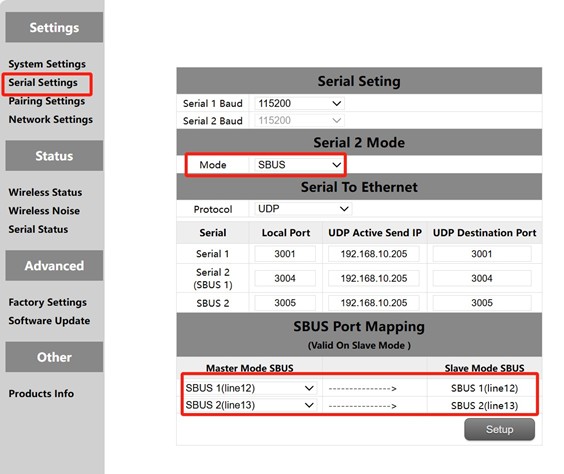
- Open the sky side and the ground side of the WEB, click the left serial port configuration.
- Change the serial port 2 mode on both the primary and secondary ends to SBUS mode.
- Change the SBUS mapping of the sky side to PIN12 input corresponding to PIN12 output, PIN13 input corresponding to PIN13 output. The SBUS mapping configuration on the ground end is invalid.
First, you need to configure serial ports 2 of the primary and secondary stations as SBUS. The module supports two SBUS. In addition, pins 12 and 13 at the ground end are SBUS inputs. Pin 12 and Pin 13 at the sky end are SBUS outputs. The 12 pins at the sky end correspond to the 12 pins at the ground end. The 13 pins at the sky end correspond to the 13 pins at the ground end
5.4.3. Serial port to network port/Network port to serial port
The function of serial switching, or network switching is mainly serial port input, network port output or network port input, serial port output, etc. The serial port on the sky end is configured as TCP or UDP for transmission. The following is an example of a Mission Planner ground station performing TCP/UDP protocol transmission.
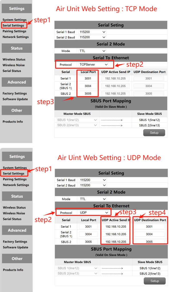
MissionPlanner (TCP mode)
TCP configuration (Air serial port)
Step 1: Open the – Serial Settings bar of the sky side web page
Step 2: Change the serial-to-network protocol to TCP server
Step 3: Determine the port number. The default port number of serial port 1 is 3001, serial port 2 is 3004. Finally click the Settings button.
MissionPlaner TCP configuration
Step 1: Open the Mission Planner
Step 2: MP Select TCP mode, do not use the serial port baud rate, click the Connect button. Enter host name/IP: 192.168.10.252(Default IP address of the sky end). Enter remote port: 3001 (serial port 1). 3004 (serial port 2).
⚫ MissionPlanner (UDP mode)
UDP configuration (Air serial port)
Step 1: Open the – Serial Settings bar of the sky side web page.
Step 2: Change the serial-to-network protocol to UDP server.
Step 3: Enter the active UDP IP address of the serial port. It is the IP address of the computer on which MP is installed.
Step 4: Determine the UDP target port number. The default target port number of serial ports 1 to 2 is 3001-3004. You can also set the target port number to different ones based on customer requirements. Finally click the Settings button.
Mission Planer UDP configuration
Step 1: Open the Mission Planner ground statio
Step 2: MP select UDP mode, the serial port baud rate is not required, click the Connect button. Enter Local port: 3001 (serial port 1). 3004 (serial port 2).
5.5. Pairing Settings
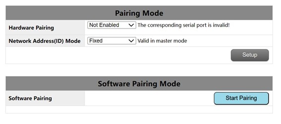
The pairing function can be realized by hardware configuration and software configuration. The ID number can be configured on the primary end to determine whether to use the random ID number or the fixed ID number of the original primary end for automatic pairing. This parameter is invalid for configuring ID mode on the secondary end.
Pairing premise:
The pair device can be paired only when it is a primary device and a secondary device. If both devices are primary devices or secondary devices, the pair cannot be paired.
Hardware pairing conditions:
- Effective within 60 seconds after starting, invalid after 60 seconds.
- Invalid in connected (synchronized) state.
- The pairing mode has been entered once after startup, and it is invalid even if
the time is still within 60s.
Hardware pairing Settings:(The Air unit and the ground unit are configured independently)
- Web configuration: Select serial port 1 or serial port 2 or serial port 4 as the
paired serial port.
- After the configuration, short connect the TX and RX of the corresponding serial port for at least 2 seconds. Customers can solder a switch button themselves by long pressing it for more than 2 seconds. TX and RX can also be
looped together.
- If the RSSI indicator blinks and turns off, the device enters the pairing mode.
Wait until the peer device also enters the pairing mode.
Software pairing Settings:
Click the “Start Pairing” button inside the page to start pairing. After 2 minutes, if
the pairing fails, the device displays the status before the pairing again.
5.6 IP configuration(Network Settings)

1.The default local IP address of the primary node is 192.168.10.250.
2.The default local IP address of the repeater node is 192.168.10.251.
3.The default local IP address of the slave node is 192.168.10.252.
4.The Alternate IP address is 192.192.192.192.(cannot be changed)
5.7 Wireless Status
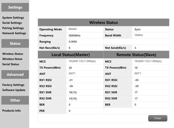
Wireless status is mainly to display channel information, such as master and slave nodes, whether to synchronize, working frequency points, distance display and network data volume statistics. It also displays the status of the local device and some information about the remote device. For example, MCS (stream mode), transmit power, twochannel received energy, two-channel received signal-to-noise ratio and error packet PER display.
The distance display can only be displayed by the master. The detection of background noise is carried out when the master is powered on. The slave does not detect background noise before synchronization. The slave detects background noise only after synchronization.
The network transmission of the master indicates the amount of data sent by the master to the PC. The network reception of the slave indicates the amount of data received by the slave from the camera.
5.8 Wireless Noise
Background noise detection is mainly used to detect ambient interference of master and slave equipment. The red line represents the bottom noise at the primary end and the blue line represents the bottom noise at the secondary end. And the lower the absolute value, the cleaner the floor noise, that is, the smaller the interference source. For example, -100dBm is better than -90dBm. Floor noise detection can quickly help customers determine whether there is interference in the test environment.
- Floor noise detection in clean environments
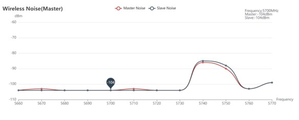
- Floor noise detection when there is interference

5.9 Factory Reset
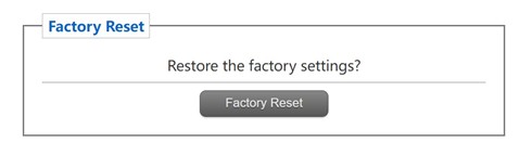
The default factory Settings of the device are the secondary (airborne) parameters, and the default network IP address after factory restoration is 192.168.10.250.
5.10 Software Upgrade
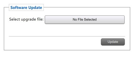
System update, for customers to update the firmware, click select file, select the corresponding burn file, after the successful upgrade, please power on again. Do not power off during the upgrade to avoid firmware loss.
5.11 Products Info

This section describes the serial number, software, and hardware version number of the device.
Ask A Question
Thank you for your response. ✨