


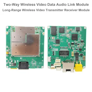
UAV Wireless Video Data RC Link for Drone 15-20-30-50-100-150km 1.4G / 2.4G / 5.8G transceiver transmitter-receiver Vcan1818


Table of Contents
Feature:
- Video Data Control 3 in 1
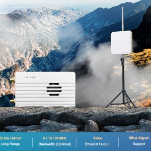
- 30-60KM wireless transmission ( 2.4G frequency, 2W: 30km; 5W: 50km; 10W: 100km)
- 4K high-definition images with low latency
- H265/H264 video compression
- Rich interface (Ethernet for IP camera, Power, SBUS, TTL, customized)
- Adaptive retransmission
- Automatic frequency hopping
Specification:
Channel bandwidth: 2.5MHz(uplink), 10MHz(downlink)
Maximum emission energy: 27dBm / 30dBm
Video format:
AV: PAL, 50INTSC, 60i
HDMI: 576i60, 480p@60fps, 720p@50fps, 720p@60fps, 1080p@50fps, 1080p@60fps
SDl: 720p@50fps, 720p@60fps, 1080p@50fps, 1080p@60fps
Modulation method: OFDM
Constellation: BPSK, QPSK, 16QAM
Forward error correction code: LDPC(1/2, 2/3, 3/4, 5/6)
Duplex mode: TDD
Downlink throughput rate: 2Mbps~8Mbps
Uplink throughput rate: 300kbps (serial port + network port + remote control)
Video interface: network port, HDMI/SDI/AV
Other interfaces: serial port, PPM/SBUS, SB
Encryption: AES128/256
Video Compression: H.264/H265(HDMI/SDI/AV)
Screen-to-screen latency: <300ms
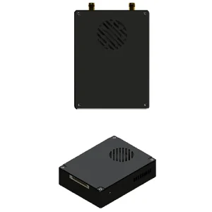
Ground end size:
92X69X24mm (network port)
Air unit size:
92X69X24mm
Weight: 195g (Vcan1818-2W-30km, 195gram)
Working temperature: -20°C-55°C

Input / Output

- MIMO connector: Power, Ethernet port, Data transmission serial port, and remote control SBUS/TTL/PPM
- USB: Connect to the computer USB, which can be used to configure and upgrade the device and other related operations.

LED
From left to right are:
Power indicator light (1)
Ethernet port indicators (3)
Uplink and downlink indicators (2).
When the wireless link is established normally, the link indicator of the air system will be off. The downlink indicator is multiplexed with the binding indicator function.
Pair button
Long press the button until the binding indicator light flashes, then release it to execute the binding operation. The factory equipment has been bound. If it is not necessary, the customer does not need to bind again.
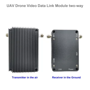
Air Unit

| No. | Interface |
| 1,2,3 | Ethernet |
| 4,5 | S.BUS, as shown in the picture, the 1st pin from the left of the Dupont connector is the S.BUS signal, and the 3rd is G. |
| 6,7 | Telemetry serial, as shown in picture, the 2nd pin from the left of GH1.25 connector is Rx, the 3rd is Tx, the 6th is G. (TTL by default, RS232/422 alternative) |
| 8 | PPM, as shown in the picture, the 1st pin from the left is the PPM signal, and the 3rd is G. |
| 9 | Power |
Ethernet 1, Ethernet 2
TTL 1 tracker, TTL2
SBUS 1, SBUS 2
Power In
Ground Unit
Vcan1818-ground-unit-IO-cable

| No. | Interface |
| 1,2,3 | Ethernet |
| 4,5 | S.BUS, as shown in picture, the 1st pin from the left is S.BUS signal, the 2nd is 5V+, the 3rd is G. |
| 6,7 | Serial-USB(TTL-USB by default, RS232/422 alternative) |
| 8 | PPM |
| 9 | Power |
Ethernet 1, Ethernet2
TTL1, TTL2
SBUS 1, SBUS 2
Power In
FAQs
- The frequency is 2410-2478 Mhz in our test video.
- This model's working frequency is customized, we also can change it to 2325 Mhz.
- Vcan1818-5W has 6Mbps at 20km, 30km, and 40km.
- Vcan1818-2W has 6Mbps at 20km, and 2-3Mbps at 30 and 40km.
- The default frequency range is 800-900Mhz
- Except 800Mhz, 1.4G and 2.4G, Other frequencies can be customized if the order quantity meets our MOQ request (50 pairs)
- The default transmitter has 2 sets of RJ45 Ethernet Video camera input.
- We also can customize 3 sets of RJ45 Ethernet video camera input when you order and notify us.
- Power Amplifier at 0.5 Watts support 2.4G and 5.8G both.
- Power Amplifier at 10 watts support 2.4G or 5.8G, it can not support two frequency bands at this 10 Watts output.
- If you choose a 10-watt power amplifier inside, it can not support 2.4G and 5.8G at the same time.
- Yes, 3G~3.9Ghz working frequency is optional. In fact, we can modify other frequencies if you need. You should have an order and agree to wait for 2 months for engineer development. (need re-layout the PCBA and small quantity to produce and test)
- Regarding automatic frequency hopping-FHSS, yes, it will auto-change to use the next working frequency if the signal is blocked or jammed.
- The drone wireless video data link module Vcan1818 power supply range: DC 18-26V.
- The antenna must be installed before powering on.
- Also, you should double check that the screws of the antenna and RF transmitter are tightened.
- Because if the antenna is not installed or the contact is poor, the power amplifier will burn out.
- You should install both two antennas on the air terminal.
- It is best to use the transmitter antenna we configure for you, ensuring that the frequency and gain of the antenna are tested and verified.
- The two antennas are best installed on both sides of the drone to ensure that the drone can still get the best signal when turning and maintain uninterrupted contact with the ground control station.
- You should install both two antennas on the ground terminal.
- It is best to use the transmitter antenna we configure for you, ensuring that the frequency and gain of the antenna are tested and verified.
-
The two ground wireless video data receiver antennas should be kept as far apart as possible.
-
They should be installed as high as possible above the ground to receive the signal from the drone transmitter.
-
The feeder cable is relatively long. For the convenience of packaging and transportation, it is bundled into a circle. In actual use, you must remember to unfold the feeder line. Do not let it remain in its original round shape, because this will invisibly create an electronic interference environment.
-
Yes, just output the standard PPM signal through the trainer port;
-
Or use the S.BUS receiver for communication.
- No, a plane can only have one air unit transmitter. If you need it to support more cameras, please tell us to offer you a better solution.
- P2P point-to-point devices can only install one ground terminal.
- P2MP point-to-multipoint devices support multiple ground terminals.
- If you have this requirement, please remember to tell us when placing your order and we can configure it for you.
- Please check whether the antenna of the drone VTX is far away from the GPS to avoid blocking interference from the GPS.
- The frequency band of 1.4G equipment is close to the GPS frequency band, so a certain degree of antenna isolation must be ensured.
- LED1 (power indicator light): After the power is turned on, the light is always blue.
- LED2~4 (network connection indicators):
- If the light is always on, it means that the physical link of the network port is connected.
- If the light is off, it means that the physical link of the network port is not connected.
- LED5 (uplink indicator):
- When the light is on, it indicates that the link between the ground unit and the air unit has been established;
- When the light is off, it indicates that the link between the ground unit and the air unit has been disconnected.
- LED6 (downlink indicator light):
- When the light is on, it indicates that the link between the air unit and the ground unit has been established;
- When the light is off, it indicates that the link between the air unit and the ground unit has been disconnected.
Please follow the steps below:
- Please check whether the power supply of the air end and ground end modules is normal;
- Please check whether the air end and the ground end are successfully bound;
- Please check whether the antenna installation of the air terminal and the ground terminal module is normal: whether there is any obstruction in the installation position of the antenna; whether the antenna interface is loose; whether the feeder is not tightened, and whether the interface is loose;
- Use the management software to check whether the transmitting frequency of the ground terminal is consistent with the receiving frequency of the air terminal;
- If none of the above operations can solve the problem, please contact our wireless video link technical support person.
Please follow the steps below:
- Please check whether the power supply of the air end and ground end modules is normal;
- Please check whether the air end and the ground end are successfully bound;
- Please check whether the antenna installation of the air terminal and the ground terminal module is normal: whether there is any obstruction in the installation position of the antenna; whether the antenna interface is loose; whether the feeder is not tightened, and whether the interface is loose;
- Use the management software to check whether the transmitting frequency of the air terminal is consistent with the receiving frequency of the ground terminal;
- If none of the above operations can solve the problem, please contact our wireless video link technical support person.
Please follow the steps below:
-
Please check whether the power supply of the air end and ground end modules is normal, and whether the modules start normally;
-
Please check whether the network cable is connected normally;
-
Please check whether the network camera is powered normally;
-
If none of the above operations can solve the problem, please contact our wireless video link technical support person.
Please follow the steps below:
-
Confirm whether the wireless link status is established normally;
-
Please check whether the connection between the flight controller and the air terminal is correct, and whether the connection between the ground terminal and the ground station is correct;
-
Please check whether the data transmission line sequence of the air end and ground end modules is normal. Our company provides standard cables. If you do the wiring yourself, please check the line sequence;
-
Check whether the data transmission baud rate is consistent with the flight control through the management software;
-
Whether the computer firewall of the ground station is closed;
-
If none of the above operations can solve the problem, please contact our wireless video link technical support person.
Please follow the steps below:
-
Confirm whether the wireless link status is established normally.
-
Please check whether the connection between the flight controller and the air terminal is correct, and whether the connection between the ground terminal and the remote control is correct;
-
If using PPM mode, please check the mode configuration of the remote control; if using S.BUS mode, please check the receiver and remote control configuration;
-
Please check whether the remote control line sequence of the air end and ground end modules is correct;
-
Check whether the remote control mode is configured correctly through the management software;
-
If none of the above operations can solve the problem, please contact our wireless video link technical support person.
Please follow the steps below:
-
Confirm whether the wireless link status is established normally;
-
Confirm whether the network physical connection indicators of the air terminal and the ground terminal are normal;
-
If using a network camera, please confirm the IP address of the network camera, login user name and password;
-
Whether the IP address configuration of the ground station computer and the network camera are in the same network segment;
-
Whether the video stream address configuration for playing RTSP is correct;
-
Whether the computer firewall of the ground station is closed;
-
If none of the above operations can solve the problem, please contact our wireless video link technical support person.
Please follow the steps below:
-
Confirm whether the downlink mode configuration is reasonable;
-
Whether the network cable used is connected properly;
-
Whether there is interference in the downlink, consider changing the working frequency point;
-
If there is no interference, whether the limit distance of the communication link has been reached;
-
Observe whether the downlink rate of the pod fluctuates too much. For example, the fixed bit rate of the pod is 3 Mbps, and the downlink rate of the client is set to 3.97 Mbps, and the peak value of the pod’s bit rate is likely to be at a certain stage If it exceeds 3.97 Mbps, there will be lag or mosaic phenomenon at this time. Set the downlink rate of the client to 5.27 Mbps, and verify whether the downlink rate exceeds 3.97 Mbps. If it exceeds 3.97 Mbps, set the downlink rate of the client to be greater than the peak value of the pod;
-
Check the real-time downlink rate of the client, whether there are double camera streams;
-
If none of the above operations can solve the problem, please contact our wireless video link technical support person.
Please follow the steps below:
-
Confirm whether the antenna and connecting cable are installed correctly and whether they are standard materials of wireless video link;
-
Ensure that the antenna installation of the air terminal will not be blocked by the load, and that there is no obvious obstruction in the short distance of the antenna of the ground terminal, and that the antenna of the air terminal and the ground terminal are perpendicular to the ground;
-
Check whether the video transmission equipment hardware such as the power amplifier is damaged;
-
Whether the downlink mode configuration value is unreasonable, and the high-speed downlink mode will significantly reduce the communication distance;
-
Whether the working frequency is significantly interfered, you can select the optimal frequency through the client;
-
Whether the air terminal and the ground terminal are seriously blocked in the flight environment, and the complex geographical environment will affect the communication distance;
-
If none of the above operations can solve the problem, please contact our wireless video link technical support person.
-
Sorry, the most used working frequency is 800Mhz, 1.4G, and 2.4G. Other frequencies should be customized.
- 443Mhz seems COFDM frequency range from 170-860Mhz, but most COFDM video transmitters and receivers are one-way transmission.
The two-way transmission model is here.


iVcan.com –
I have been using the Vcan1818 UAV Wireless Video Data RC Link for several months, and it has exceeded my expectations. The video quality is excellent with 4K resolution and low latency, making real-time monitoring smooth and reliable. Setup is straightforward, and the adaptive frequency hopping ensures a stable connection even in complex electromagnetic environments. The long-distance transmission up to 100km is impressive, and the H265/H264 compression combined with AES encryption provides both efficiency and security. The multiple interfaces, including HDMI, SDI, AV, Ethernet, and SBUS, offer great flexibility for different UAV applications. Overall, this module delivers professional-grade performance for drone video and data transmission.