




Introduction
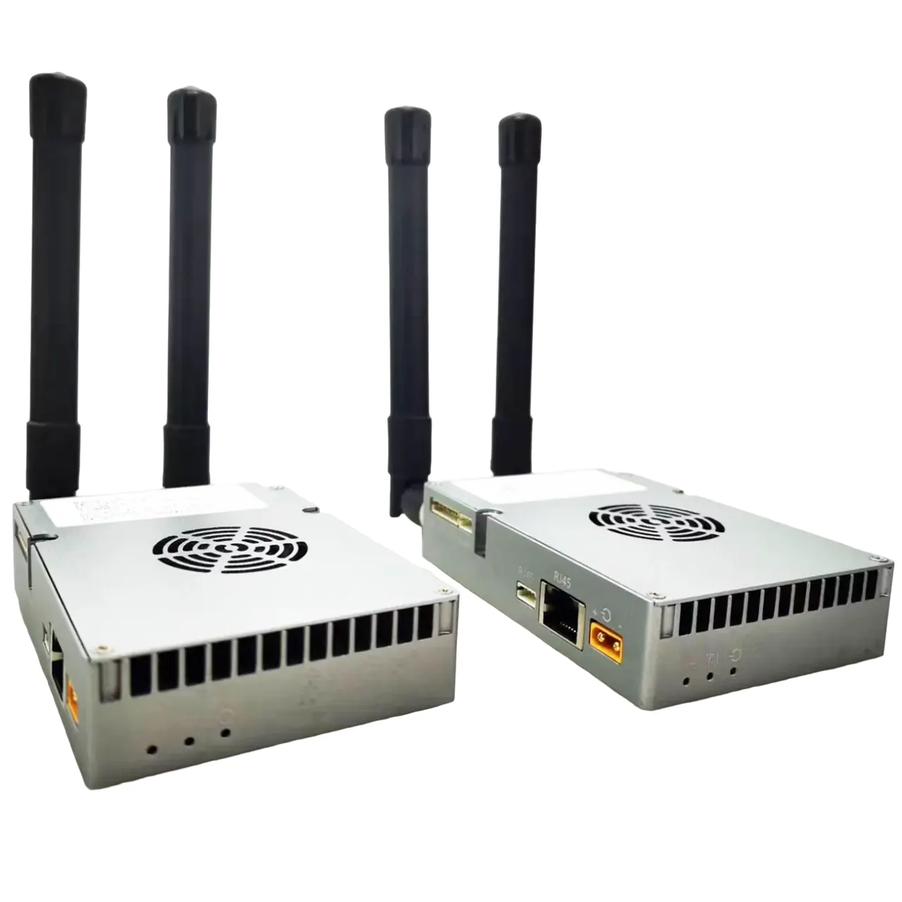
Many users connect their UAVs to ground computers using our 2-way wireless link TX900 to operate Mission Planner. The air-side connects via TTL to the flight controller, while the ground side uses a serial-to-network method.
Some connection issues occur when users modify the link default parameters. To ensure reliable operation, it is critical to use the default parameter settings. In this guide, we provide step-by-step screenshots of the default configuration, so you can match your setup exactly.
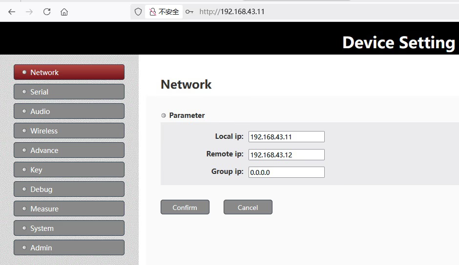
Please noted that the user’s computer ip address is 192.168.43.xxx, so we modify our setting to meet his computer’s ip address.
Here is another introduction post.
https://ivcan.com/p/video-telemetry-downlink-flight-control-commands-uplink/
Here is operation video at youtube.
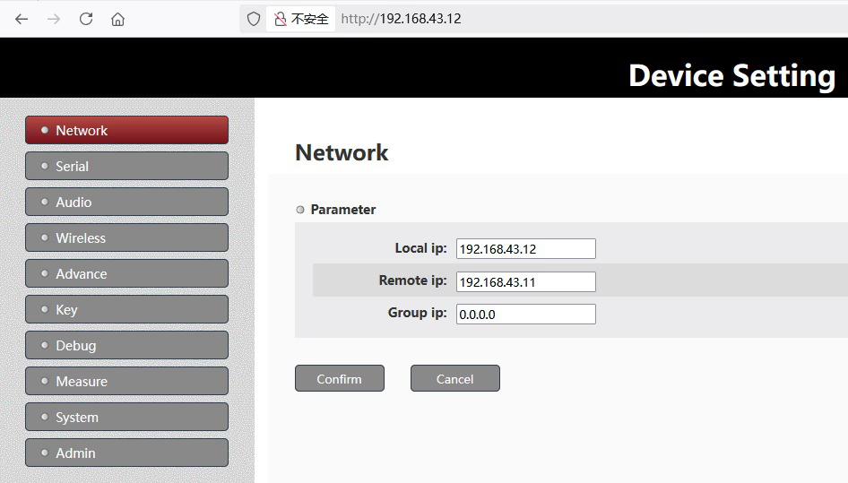
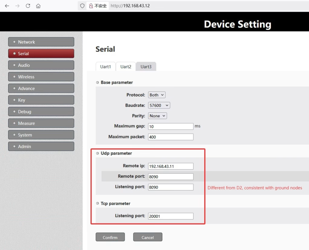
Step 1: Air-Side (UAV 192.168.1.12, access node) Settings
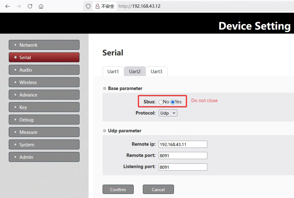
The UAV connects to the wireless module via TTL. Screenshot Example:
Step 2: Ground-Side (PC, 192.168.1.11, central node) Settings
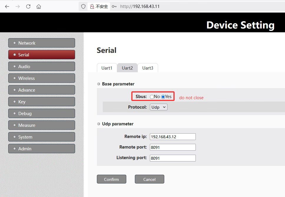
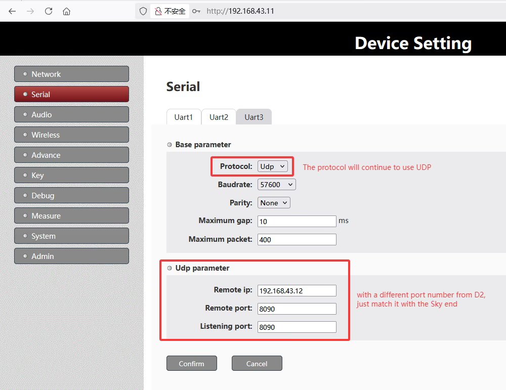
On the ground, a serial-to-network conversion is used to link the PC running Mission Planner. Screenshot Example
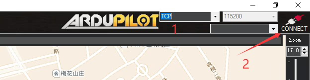
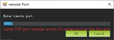
Step 3: Using MissionPlanner.exe on the Ground-side

Step 4: Parameter Alignment
To ensure successful connection:
- Each parameter page on both air-side and ground-side must match the default configuration.
- Avoid changing TDD time slot ratios or baud rates unless advised by our engineers.
- Verify the network settings and IP addresses of your serial-to-network adapter match the UAV module.
Step 5: Testing the Connection
After confirming default parameters:
- Power on both UAV and ground station.
- Open Mission Planner on the ground PC.
- Connect to the UAV via the wireless link.
- If the connection is unstable, re-check the parameters on both sides and ensure they match the defaults exactly.
Caution
If, after configuring the web parameters according to our screenshots, the telemetry data still cannot be received, then double-check the serial connection between the air-side node’s D3 port and the customer’s flight controller.
Make sure that:
- The voltage levels are compatible.
- Tx and Rx lines are not reversed.
Please remind to power cycle both the air-side and ground-side nodes to ensure the parameters take effect.
Ask them to check the serial connection between the air-side node’s D3 port and the flight controller, making sure that Tx and Rx are not reversed.
Please try to ping 192.168.43.12 from your PC to see if it responds. This will help confirm whether the wireless link is working properly.
At present, the customer’s air-side node interface is set to Both, which means it is running a TCP server (port 20001) and also actively sending serial data via UDP to the PC at IP address 192.168.43.2, UDP port 8090.
Based on this configuration, the ground-side MissionPlanner.exe can access the telemetry data in either of the following ways:
TCP mode: Connect to the air-side node’s IP (192.168.43.12) and TCP port (20001), as shown in the screenshot from point 3 above.
UDP mode: Receive telemetry data via UDP on the PC’s IP (192.168.43.2) and port (8090).
The customer can even open a network debugging tool to check whether any telemetry data from the flight controller is being received.
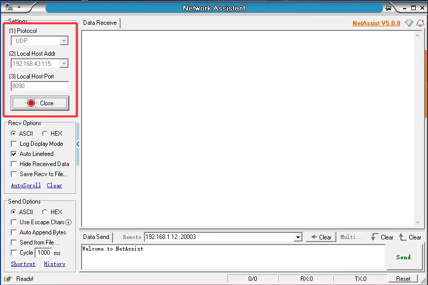
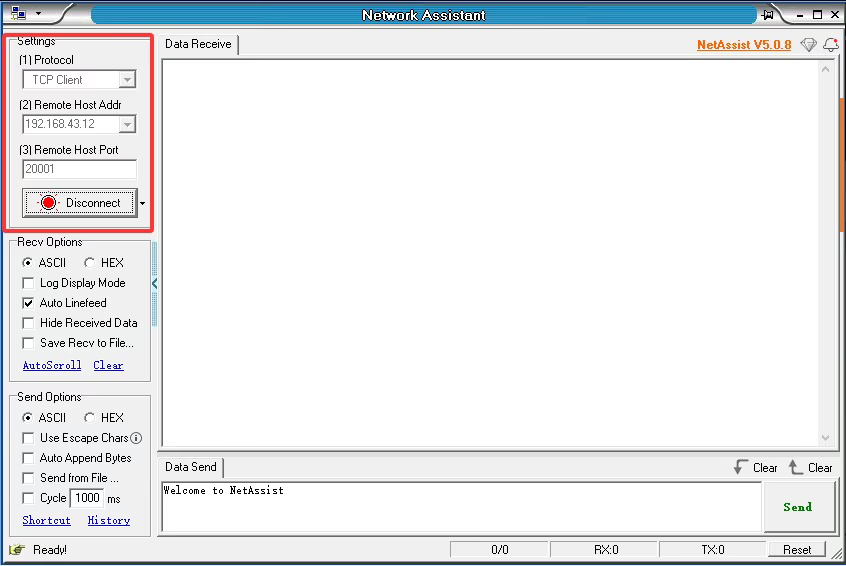
Note: My PC’s IP address is 192.168.43.115, not 192.168.43.2 as in the customer’s setup.
FAQ
Q: The customer asked why the two devices—one air unit and one ground unit—show different LED behaviors when powered on. One LED is Alway light on, while the other is blinking. Why is that?
A: Drone side is access node, ground side is central node.

Node LED: blue light for Node type indictor: 1. Continuous light when the device worked as Centrol Node(ground unit, 192.168.1.11). 2. blink light when the device worked as Access Node (air unit, 192.168.1.12).
Conclusion
Using default parameters is essential for stable two-way communication between your UAV and ground PC. Follow the screenshots and guidance in this post to configure the link correctly. Any changes may prevent Mission Planner from operating successfully.
Ask A Question
Thank you for your response. ✨