Table of Contents
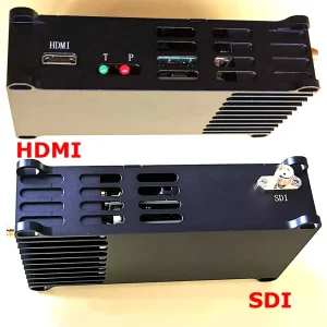
Encode Board for COFDM Wireless Video Transmitter


- Ultra-low latency H.265/H.264 audio and video encoding, maximum support for 1080P@60 real-time audio and video capture encoding
- Mini HDMI or AV audio and video input, encoded after the Ethernet port output or output to the 矽Hida wireless transmission module, the video encoding rate can be dynamically configured through the serial port
- Support audio input and audio decoding output
- Supports two channels of video simultaneous input coding (option)
Feature
This Encode Board implements H.265/H.264 audio and video compression coding, supports up to 1080P@60fps encoding, and is backward compatible with other various resolution and frame rate encoding.
-
- Audio and video input
- Mini HDMI interface (audio + video): 1080 60P, 1080 50P, 1080 30P, 1080 25P, 1080 60I, 1080 50I, 720 60P, 720 50P, 720 30P, …, various modes of adaptation;
- AV in interface (audio + video): 720×480 60I (NTSC), 720×576 50I (PAL), mode adaptive. When inputting audio through the AV interface, it can be either Line-in or Microphone in.
- After the system is powered on, the audio and video input source is automatically detected. The default audio input is the same as the video input interface. The audio input interface can also be configured through the configuration of the serial port. When the HDMI and AV audio and video sources are connected at the same time, the system preferentially captures the HDMI audio and video source by default. The signal is encoded, and the audio and video source collection interface can also be configured through the configuration serial port, and the audio and video source collection interface can be dynamically switched through the serial port command during system operation.
Video coding: H.265 or H.264 format, the code rate can be configured through the configuration serial port.
Audio coding: AAC coding.
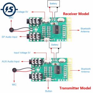
- Audio output (Speaker interface)
This Encode board can be connected to the speaker through the Speaker interface to decode and play the input audio when docking the other two-way wireless transmission module RCD or other bidirectional links. - Ethernet port (Ethernet interface)
Supports docking with another wireless transmission module, or other two-way wireless links. - Wireless transmission interface (FPC_Main interface)
It can be connected to the other COFDM wireless transmission module RCA, RCB, etc., and can also be connected to another two-way wireless transmission module RCD. - Data serial port (Data-UART)
TTL 3.3V level, transmission baud rate and other parameters can be configured through the configuration of the serial port. When this Encode board is connected to another wireless transmission module, the data serial port is used for one-way transparent data transmission. - Parametric serial port (CFG-UART)
TTL 3.3V level can be connected to another parameter configuration panel or another host computer, used to configure the operating parameters of this Encode board system. Please contact us for detailed matching agreement. - USB Host interface Software upgrade maintenance.
- Supply voltage
Support power supply reverses connection protection, support power input range of 7~24V. Provide a 5V power output interface. The maximum operating power of this Encode board is 2.28W (1080P60 H.265 encoding), and the maximum current is 190mA when the 12V power supply is working. - Indicator light
Power indicator, video signal detection lock indicator, video coding work indicator. - Board size
70*45mm (excluding the size of the interface device extending from the edge of the board), the board thickness is 1.2mm, the height of the back component is less than 2mm, and the height of the front component is less than 4mm (when the power input does not use PH2.0 carrier, the power input PH2. 0 seat height is less than 5mm). - Board weight
This Encode board weighs 15.5 grams.
- Audio and video input
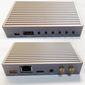
Interface Define
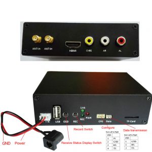
Power and indicator
The power input interface is a 2PIN 2.0mm pitch female. Two pairs of 2PIN power supply holes are reserved on the board. One pair of power supply holes are directly connected to the power input signal, and the other pair of power supply holes are exposed after anti-reverse protection. This Encode board also provides a 5V power output interface, which is convenient for the user to supply power to the cooling fan when needed. The figure below shows the power pin signals and indicators.

LED1: Power operation indicator, always on after power-on;
LED2: Video signal detection lock indicator light, this Encode board will automatically lock after detecting the video source. If the LED is not lit, the system fails to collect the video source.
LED3: Video coding work indicator, flashing during normal operation.
AV Interface, Serial port, USB port, Ethernet port, audio output interface

- AV-in: Analog audio and video input interface, 6PIN 1.25mm pitch carrier, audio support Mic in or Line-in input.
ML (Mic in light), audio Mic input left channel;
MR (Mic in right), audio Mic input right channel;
LL (Line-in light), audio Line in left channel;
LR (Line in right), audio Line in the right channel;
GND, signal ground;
AV, analog video input. - CFG-UART: equipped with a serial port, 4PIN 1.25mm pitch carrier, used for this Encode Board parameter configuration, can be connected to Haida parameter configuration panel or another upper computer. See the above figure for each PIN pin signal.
- Data-UART: Data serial port, 3PIN 1.25mm pitch carrier, transmission baud rate and other parameters can be configured through the configuration of the serial port. When this Encode board is connected to another wireless transmission module, the data serial port is used for one-way transparent data transmission. See the figure above for each PIN pin signal.
- USB interface: 4PIN 1.25mm pitch carrier for This Encode Board software upgrade maintenance.
- Speaker: 2PIN 1.25mm pitch carrier, This Encode Board can be connected to the speaker through the Speaker interface. When this Encode Board is connected to the Haida two-way wireless transmission module RCD or other bidirectional links, the input audio is decoded and played, and output to the speaker. PIN foot signal:
- SP: Speaker out-P
- SN: Speaker out-N
- Ethernet: Ethernet interface, 4PIN 1.25mm pitch carrier, refer to the above figure for each PIN pin signal. Usually, the connector is not soldered when shipped by default.
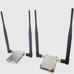
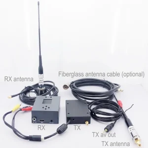
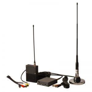
Application
It can be assembled with another COFDM modulation module RCA, RCB, RC900, etc. to form COFDM transmitters with different functions, and the connection interfaces are all FPC_Main (26PIN flat cable).


It can also be assembled with another two-way wireless transmission module RCD stack to form a two-way wireless transmission video transmitter, and the connection interface is also the FPC_Main interface.


It can be connected to the parameter configuration panel (SconA, SconB, SconC, etc.) through the CFG-UART interface to set the operating parameters.

Encoder Modules Boards


Decoder Modules Boards


Available for Customization
New Encoder Products
| No. | Product Name | Configuration | Key Features | Status |
|---|---|---|---|---|
| 1 | Dual-Channel USB UVC Visible Light Video Encoder | 2× USB input | Supports dual USB camera video encoding, and RTSP streaming; local CVBS/HDMI output; switchable display modes | Mass Production |
| 2 | Dual-Channel Encoder (1× USB Visible Light + 1× USB Thermal Imaging camera) | 2× USB input | Supports dual USB camera (visible + thermal) capture, encoding, and RTSP streaming; local CVBS/HDMI output; switchable display modes | Mass Production |
| 3 | RTSP Decoder HDMI/CVBS Display Module | HDMI + CVBS output | Supports up to 4×1080P@30fps RTSP stream decoding; Support video streaming protocol forwarding; HDMI/CVBS output display | Sample Available |
| 4 | RTSP Decoder HDMI/CVBS Display Module with 4.3"/5" LCD | HDMI output + LCD screen | Supports up to 4×1080P@30fps RTSP stream decoding; protocol forwarding; HDMI/CVBS output display | Debugging |
| 5 | Dual-Channel Encoder (1× USB Visible Light + 1× CVBS Analog) | 1× CVBS + 1× USB UVC input | Dual video (USB + CVBS), encoding and RTSP streaming; local CVBS/HDMI output; switchable display modes | Debugging |
| 6 | Dual-Channel Encoder (1× USB UVC + 1× AHD Analog) | 1× AHD + 1× USB UVC input | Dual video capture (USB + AHD), encoding and RTSP streaming; local CVBS/HDMI output; switchable display modes | Debugging |
| 7 | Dual-Channel Encoder (1× CVBS + 1× AHD Analog Video) | CVBS + AHD 2 video input | Dual analog video capture, encoding and RTSP streaming; local CVBS/HDMI output; switchable display modes | Debugging |
| 8 | Dual-Channel Encoder (1× CMOS Camera + 1× USB Thermal Imaging camera) | 1× USB interface | Supports CMOS + USB thermal camera capture, encoding and RTSP streaming; local CVBS/HDMI output; switchable display modes | Mass Production |
For customized video input/output conversion solutions not listed in our products, please contact us for OEM/ODM support. We can develop tailored products based on your requirements.