


4K HDMI Video Encoder Decoder Board HDMI to Ethernet and Ethernet to HDMI RTSP UDP

Table of Contents
Feature
- Low Latency Video Encoder/Decoder: Supports H.265/H.264 encoding and decoding with full HD resolution, up to 3840x2160P at 30 frames per second.
- Audio Codec: Includes audio input and output capabilities.
- Video Encoding Functionality:
- Input: HDMI
- Output: Streams via Ethernet using RTSP/TS protocols
- Protocols Supported: TCP and UDP
- Video Decoding Functionality:
- Input: Streams via Ethernet using RTSP/TS protocols (TCP and UDP)
- Output: HDMI
- Management Interface: Accessible via a web UI or UART.
- Pairing Capability: The one 4K encoder can be paired with another 4K decoder for low latency operation, achieving approximately 100ms latency for 1080P60 H.265 video.
Introduction
Specification

IO
| HD video input | HDMI, type A connector. |
| HD video output | HDMI, type A connector. |
| Analog audio input / output | 3PIN PH1.25mm connector. |
| Data UART | 3PIN PH1.25mm connector, TTL 3.3V, baud rate adjustable. |
| Control-UART | 4PIN PH1.25mm connector, TTL 3.3V, baud rate adjustable. |
| USB Host | 4PIN PH1.25mm connector, for software upgrading and USB disk recording When works as video decoder. |
| Power in | 2PIN PH2.0mm connector. |
| Ethernet1 | 4PIN PH1.25mm connector. |
| Ethernet2 | 4PIN PH1.25mm connector. |
| FPC_main | To connect with our COFDM modulator. |
Video and Audio
| Video input / output | HDMI |
| Video formats | 3840P30, 3840P25, 3840P24, 1080P60, 1080P50, 1080I60, 1080I50, 1080P30, 1080P25, 720P60, 720P50, 720P30, …… |
| Video
encoding or decoding |
H.265/H.264, setup via control UART or Web UI;
Bitrates adjustable; Supports proprietary H.265/H.264 video compression only used p-frames for the lowest latency(the 4K encoding plus 4K decoding latency is about 130ms for 1080P60 video). |
| Audio input / output | Embedded HDMI or analog audio. |
| Audio Coding | AAC, 16bit, mono, 48Kbps |
| Ethernet stream protocol | UDP TS stream, RTSP stream, UDP TS stream + RTSP stream |
Monitoring and control
Comprehensive setup via web UI or AT command via control UART.
Temperature range
Full specification: 0° to +70°C Ambient (Optional: -40° to +85°C )
Storage:–40° to +85°C
Physical Characteristics
Dimensions: 80*50mm(not including connectors out of the board)
Weight: 27g
Power requirements
Input range: 7~30VDC
Power consumption: <250mA@12V
I/O signals

The power input interface is a 2PIN PH2.0mm connector. The module board also provides a 5V power output for fan that it may be required when the module is integrated with wireless modules.
Data UART
The 4K module supports one channel uart data packed with the stream and transmitted via the Ethernet. When 4K encoder works paired with 4K decoder and Ethernet linker (wireless or wire), the data to this uart will be transferred to the remote 4K uart.
Control UART
4PIN PH1.25mm connector, TTL 3.3V. The 4K board system can be set-up via this control uart with AT command.
Audio in and Audio out
3PIN PH1.25mm connector. When 4K encoder board works paired with 4K decoder board and Ethernet linker (wireless or wire), it supports bidirectional voice communication. The analog audio input can be line in or Mic in, the analog audio out is designed to output to earphone or audio amplifier.
Ethernet1 and Ethernet2
Two 4PIN PH1.25mm connector, 100M ethernet port.
When the 4K board is shipped as an independent encoding or decoding board, Ethernet1 and Ethernet2 are internally set to bridge, with the same IP addresses for both network ports. The input or output of video data is through the Ethernet1 interface, and Web UI access is through the Ethernet2 interface; Ethernet1 supports connecting with our bidirectional wireless transmission modules or other third-party bidirectional linkers. Ethernet1 supports UDP TS stream, RTSP stream and UDP TS stream + RTSP stream.
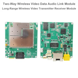
When using the 4K board with our COFDM wireless transmitter modulator module (connected through FPC-Main interface via flat cable), Ethernet1 and Ethernet2 are internally set as two independent network ports, with different IP addresses.For this application, the Ethernet1 interface cannot be used externally because network signals are multiplexed to the FPC-Main interface.The Ethernet2 interface can be used as an access network port for the Web UI, or can connect to the IP camera through the Ethernet2 network port. The IP camera video signal can be transmitted through the COFDM wireless module modulator. The below picture shows 4K module connecting with our COFDM transmitter modulator module.
4K& COFDM transmitter modulator module
LEDs and GPIO
There are three signal indicator lights (LED1/LED2/LED3) on the right side of the 4K module board, and the indicator light signals are simultaneously connected to the J6011 connector PINs (4PIN 1.25mm connector). Some customers may need to assemble indicator LEDs on their housing case, then they can use J6011 connector PINs to add indicator LEDs on their housing case.
When the 4K works as an encoding board, the corresponding signals of the indicator lights are as follows:
| LEDs | Description | Corresponding J6011 PIN |
| LED1 | Power-LED: red color, constant light when the board is normally powered. | LED1-PIN |
| LED2 | Green color, constant light when the input video is detected successfully, otherwise it will not light. | LED2-PIN |
| LED3 | Encoding-LED: green color, blinks when video encoding normally. | LED3-PIN |
When the 4K works as a decoding board, the corresponding signals of the indicator lights are as follows:
| LEDs | Description | Corresponding J6011 PIN |
| LED1 | Power-LED: red color, constant light when the board is normal powered. | LED1-PIN |
| LED2 | Green color, constant light when video is being recorded with USB disk, otherwise it will not light. | LED2-PIN |
| LED3 | Decoding-LED, green color, blinks when video stream is normal received and decoding | LED3-PIN |
When using J6011 PIN signal to connect LED indicator lights externally, the “positive pin” of the external LED2 and LED3 indicator lights should be connected to the corresponding J6011 PIN, and the “negative pin” should be connected to any GND on the 4K board; When connecting the external LED1 power indicator light, connect the “positive pin” to the J6011 LED1-PIN and the “negative pin” to any GND on the 4K board.
GPIO signal on J6011 connector: reserved GPIO for using as special customized software.
FAQ
Q1: Does it support CVBS analog video input?
A1: No, only HDMI video input.
Q2: Can you offer me with a metal box?
A2: Sure, Please check the below pictures.


Q: What is the difference between the 4K decoder board I purchased and the other 4K + CVBS decoder board (model 2227)?
A: Our engineer would like to remind you that the 4K board you purchased supports both encoding and decoding. However, when used as a decoder, it only supports up to 4K at 30 FPS.
If you require 4K at 60 FPS, we recommend the alternative model 2227 board. This board:
- Supports 4K 60 FPS decoding
- Is slightly larger in size
- Supports CVBS video output
- Is offered at the same price
Applications
- Real-Time Aerial Video Streaming
The board can be used for real-time video streaming from drones to ground control stations, providing high-quality 4K video feeds for surveillance, mapping, and inspection. Its low-latency encoding and decoding capabilities make it ideal for live broadcast scenarios, where high-quality, real-time video is crucial for decision-making.
- Aerial Surveillance & Monitoring
Drones equipped with the 4K HDMI encoder can be used for aerial surveillance, capturing 4K video from high altitudes and transmitting it over Ethernet or wireless links. This is particularly useful for public safety, military reconnaissance, or environmental monitoring. The ability to stream video in HD or 4K resolution ensures clarity for critical operations.
- Drones for Search & Rescue Operations
In search and rescue missions, drones need to transmit live video feeds to ground crews to locate missing persons or assess disaster zones. The encoder-decoder module allows for seamless HD/4K video transmission, even in challenging environments, helping rescue teams get crucial, real-time visual information from the drone.
- Inspection of Infrastructure and Critical Assets
Drones are increasingly being used for inspecting infrastructure such as power lines, bridges, and oil pipelines. The encoder module allows for high-definition video recording and streaming to ground systems, enabling remote inspections and reducing the need for manual inspections in dangerous or hard-to-reach areas.
- Broadcasting and Live Streaming from UAVs
The board’s capability to stream high-definition video with low latency makes it perfect for live broadcasting applications, such as sports events, aerial cinematography, or drone racing. The ability to handle real-time, high-quality video streaming is essential for professional-grade broadcasts.
- Integrated with COFDM for Wireless Communication
When paired with a COFDM (Coded Orthogonal Frequency Division Multiplexing) module, this encoder-decoder system is perfect for creating a long-range, wireless communication link between drones and ground stations. This integration allows for reliable, high-quality video transmission even in non-line-of-sight (NLOS) environments.
- Remote Control and Telemetry Data Transmission
The module can transmit not only video data but also telemetry data (via UART) over the same Ethernet link. This is essential for remote control of UAVs and monitoring flight parameters (e.g., altitude, speed, battery life) in real-time.
- Military and Defense Applications
In military settings, UAVs are used for intelligence gathering, reconnaissance, and surveillance. The encoder-decoder board ensures the secure and efficient transmission of HD/4K video streams to ground units, offering strategic advantages during operations in areas with poor or unstable connectivity.
- Agricultural Drones
Drones used in precision agriculture can benefit from high-definition video streaming for crop monitoring and field inspections. The encoder module allows for the transmission of detailed video, helping agricultural experts monitor large areas efficiently and make timely decisions based on visual data.
- Training and Simulation
In drone training and simulation environments, the board enables the real-time transmission of live drone footage to instructors and students. This makes it easier to provide training sessions and simulate real-life scenarios that require visual observation and tactical decision-making.
Customization Options
- Video Resolution and Frame Rate:
- The board supports 4K (3840x2160P) resolution at 30 fps and can be configured for other resolutions such as 1080P60, 1080P50, and 720P60. You can select the resolution and frame rate based on the specific needs of your project.
- Custom Firmware:
- The module can be equipped with optional firmware to support additional features such as split-screen mode for displaying up to four 1080P video channels. You can also request modifications to the firmware to suit unique application requirements.
- Audio Options:
- The board supports both HDMI embedded audio and analog audio input/output, which can be configured for your specific system. You can also choose different audio codecs such as AAC (16bit, mono, 48Kbps) to meet your needs.
- Control Interface Customization:
- The management interface can be customized either via a web UI or a UART control interface. You can request custom control protocols or configurations for better integration with your existing system.
- Network Protocol Customization:
- The board supports multiple Ethernet streaming protocols, including UDP TS stream, RTSP stream, and a combined UDP TS + RTSP stream. Depending on your network infrastructure, you can adjust the protocol settings to suit your environment.
- Physical Enclosure:
- The module can be delivered with a customized metal box or housing, providing additional protection and mounting options. The box can also include customized connectors or slots for easy integration into your system.
- GPIO and LED Indicators:
- The GPIO signal and the LED indicators can be customized for specific signaling needs. For example, you can integrate external LED indicators or customize the control signals via the J6011 connector.
- Power Input/Output:
- The power input can be customized to suit your device’s power requirements, ranging from 7V to 30V DC. Additionally, the module offers a 5V power output for use with cooling fans or other components in integrated systems.
- Temperature Range:
- The module comes with standard temperature specifications (0° to +70°C), but for demanding environments, it can be customized to handle a wider temperature range from -40° to +85°C.
This board can be tailored in a variety of ways to fit your specific video streaming, encoding/decoding, and networking needs. Let me know if you need any further details or specific configurations!
Encoder Modules Boards


Decoder Modules Boards


Available for Customization
New Encoder Products
| No. | Product Name | Configuration | Key Features | Status |
|---|---|---|---|---|
| 1 | Dual-Channel USB UVC Visible Light Video Encoder | 2× USB input | Supports dual USB camera video encoding, and RTSP streaming; local CVBS/HDMI output; switchable display modes | Mass Production |
| 2 | Dual-Channel Encoder (1× USB Visible Light + 1× USB Thermal Imaging camera) | 2× USB input | Supports dual USB camera (visible + thermal) capture, encoding, and RTSP streaming; local CVBS/HDMI output; switchable display modes | Mass Production |
| 3 | RTSP Decoder HDMI/CVBS Display Module | HDMI + CVBS output | Supports up to 4×1080P@30fps RTSP stream decoding; Support video streaming protocol forwarding; HDMI/CVBS output display | Sample Available |
| 4 | RTSP Decoder HDMI/CVBS Display Module with 4.3"/5" LCD | HDMI output + LCD screen | Supports up to 4×1080P@30fps RTSP stream decoding; protocol forwarding; HDMI/CVBS output display | Debugging |
| 5 | Dual-Channel Encoder (1× USB Visible Light + 1× CVBS Analog) | 1× CVBS + 1× USB UVC input | Dual video (USB + CVBS), encoding and RTSP streaming; local CVBS/HDMI output; switchable display modes | Debugging |
| 6 | Dual-Channel Encoder (1× USB UVC + 1× AHD Analog) | 1× AHD + 1× USB UVC input | Dual video capture (USB + AHD), encoding and RTSP streaming; local CVBS/HDMI output; switchable display modes | Debugging |
| 7 | Dual-Channel Encoder (1× CVBS + 1× AHD Analog Video) | CVBS + AHD 2 video input | Dual analog video capture, encoding and RTSP streaming; local CVBS/HDMI output; switchable display modes | Debugging |
| 8 | Dual-Channel Encoder (1× CMOS Camera + 1× USB Thermal Imaging camera) | 1× USB interface | Supports CMOS + USB thermal camera capture, encoding and RTSP streaming; local CVBS/HDMI output; switchable display modes | Mass Production |
For customized video input/output conversion solutions not listed in our products, please contact us for OEM/ODM support. We can develop tailored products based on your requirements.


John –
This 4K HDMI encoder/decoder board is a game-changer! I was amazed how effortlessly it converted HDMI to Ethernet and back, eliminating long cable hassles. The 4K video stays crisp, and RTSP/UDP support lets me stream flawlessly to multiple devices. Setup was surprisingly simple—no lag or glitches during intense video sessions. Perfect for professional installations or remote monitoring. Reliable, high-quality, and truly versatile. Highly recommend for anyone needing robust HDMI-over-IP solutions!