


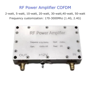
2 Watts or 5 Watts or 10 watts PA Linear Power Amplifier RF module board PCBA for wireless video data link transmitter TDD

This is a key part of a wireless video transmitter, which can enlarge the RF signal for a longer range and distance. Optional 1 Watt, 2 Watt, 5 Watt, and 10 Watt.
Table of Contents
Features
- Frequency band: 800Mhz-830Mhz, 1425MHz-1455MH
- RF in: 25±2dBm
- RF out power: 2 Watt (33dBm)
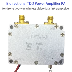
- 1400Mhz Transmitter gains 11dB when used with a two-way wireless video data link module, set up the maximum RF power as 22~24 dBm, then the RF out power will be 33~35 dBm.
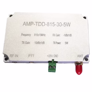
- 800Mhz Transmitter gain: 13dB, when used with a two-way wireless video data link module, set up the maximum RF power as 20~22 dBm, then the RF out power will be 33~35 dBm.
- RF out power: 5 Watt (37dBm)
- 1400Mhz Transmitter gains 15dB when used with a two-way wireless video data link module, set up the maximum RF power as 22~25 dBm, then the RF out power will be 37~37 dBm.
- 800Mhz Transmitter gain: 17dB, when used with a two-way wireless video data link module, set up the maximum RF power as 20~22 dBm, then the RF out power will be 37~39 dBm.
- RF out power: 10 Watt (40dBm)
- TX gain: 18dB, when used with a two-way wireless video data link module, set up the maximum RF power of as 22~24 dBm, then the RF out power will be 40~42 dBm.
- 2 Watts Power in DC12V~16V;
- 5 Watts Power in DC24V~25V, minimum 1.8A@24V power current rating
- 10 Watts Power in DC24V~30V, minimum 2.5A@28V power current rating
- 2 Watts Power consumption: <6W average; 5 Watts Power consumption: <14W average; 10 Watts Power consumption: <28W average
- 2 Watts 5 Watts PCBA size: 46.5*31mm, the thickness of PCB: 1.2mm
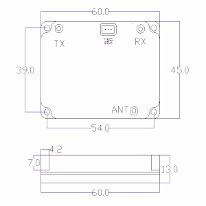
- 10 Watts Dimensions: 65*62*13.5mm, not including the connector out of the metal housing, Weight: 98g
- Impedance: 50 ohm
Working together with a two-way wireless video data link Module:

RF Input

RF Output

| Power in | We should solder two bonding pads to connect with power VDD and GND. |
| Control | We should solder two bonding pads to connect with a two-way wireless video data link module Switch signal pad(SCL and GND). The input high (1.8V to 3.3V) will drive the amplifier and work in transmitter mode. The input low will enable the PA module to work in receiver mode. |
| RF in | IPEX connector for connection with the main antenna of the two-way wireless video data link module. |
| RF out | We should solder the bonding pad to an antenna connector. |


Housing case and assemble
We recommend that this power amplifier for our two-way wireless video data link OEM PCBA module.
To enhance the power amplifier in conjunction with our two-way wireless video data link module, we recommend you fabricate a metallic housing casing that aligns with your device’s architecture.
It should also leave at least 6mm between the PA board and the upper cover. In order to facilitate heat dissipation and establish an electrical grounding connection, the back side of the PA board must be directly and firmly attached to the metal.
Proper integration of heat dissipation techniques, such as a heat sink or fan, is essential for optimal performance in designs utilizing the PA OEM module.
We can also make a metal chamber for this PA module according to the customer’s requirement.
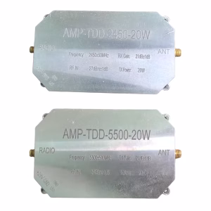
The below model has a built-in Power Amplifier inside.

FAQ:
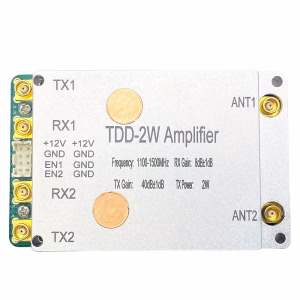
Q: Could you tell me your RF power amplifier dimension size? I want to design my enclosure.
A: Please check the below picture. And tell us if you need any further information.

Q: Could you show me the real photos of your RF linear power amplifier?
A: sure, please check the below pictures.
Q: Are you not using the TQP7M9104 amplifier in the 2W module?
A: No


Reviews
There are no reviews yet.