


Micro COFDM Video Transmitter FPV1887 Wireless Video Transmission System Users Manual

Table of Contents
Micro COFDM Video Transmitter FPV1887 Feature
- Highly integrated, modular combined design
- Using COFDM modulation technology and H.265 encoding technology
- Can simultaneously transmit one channel of analog video signal and one channel of unidirectional data supporting the highest rate of 230400bps
- Low latency, end-to-end latency minimum 120ms
- Omni-directional communication, extremely strong diffraction performance
- High-speed on-the-go communication
- Transmitter heat sink aluminum casing, shockproof and impact-resistant
- Non-line-of-sight (NLOS) mobile transmission, ground transmission, when the sending and receiving height is 3 meters, the transmission distance is not less than 3Km, and the distance under line-of-sight conditions is not less than 30 kilometers (with slight non-co-frequency electromagnetic interference), the furthest The distance can reach more than 100Km (the electromagnetic environment is clean)
- The maximum moving speed can reach 600Km/hour (actual measurement)
- The receiver video signal is synchronously outputted in high-definition HDMI1080P with multiple formats optional, and standard-definition outputs DVD image quality
- The receiver can realize video recording and backup functions
- 128-bit AES encryption and decryption
- Full customization available
Mirco COFDM Video Transmitter FPV1887 Application
This product is mainly used in technical reconnaissance and evidence collection by public security and safety inspection departments. Because of its extremely strong diffraction performance and narrow-band high anti-interference ability, this product is particularly suitable for video transmission of low-altitude, high-speed drones and ground unmanned equipment.

The relationship between transmission distance and height
Micro COFDM Video Transmitter Parameter Indicators
COFDM Video Transmitter Appearance (only standardized pictures, except for customization)

Whole machine sample drawing

COFDM Video Transmitter Specification
| Modulation method | COFDM |
| Working Voltage | DC11V~DC18V |
| Working Current | Mainboard current: 160mA; whole machine current: 0.5-Watt PA @≤0.6A DC12V; 1-Watt PA @≤0.8A DC12V; 2-Watt PA @≤1.1A DC12V; 3-Watt PA @≤1.8A DC12V, |
| Control Interface | Standard RS232 interface: 8 data bits 1 stop bit Even parity Baud rate: 19200 |
| transparent Data interface | A one-way transparent serial port transmission 8 data bits 1 stop bit Supports odd parity, Even parity, Wireless parity, Baud rate: 1200, 2400, 4800, 9600, 19200, 38400, 57600, 115200 ,230400 |
| Encryption Method | 128-bit AES encryption |
| Modulation Mapping | QPSK (4QAM), 16QAM, 64QAM (factory default is QPSK) |
| Forward Error Correction | 1/2 2/3 3/4 5/6 7/8 (factory default is 1/2) |
| Guard Interval | 1/32 1/16 1/8 1/4 (factory default is 1/32) |
| Number of Carriers | 2K |
| Frequency Bandwidth | 2/3/4/5/6/7/8M adjustable (factory setting is 2MHz) |
| Transport Stream | 1200kbs~20000kbs adjustable (factory default is 1500kbs) |
| Transmit Power | Motherboard output power: -7dBm (average power); Overall machine output: 0.5W/1W/2W/3W/5W (customized) |
| Transmission Frequency | 170-2900MHz frequency is continuously adjustable With a step of 100KHz (the default frequency of the tuner is 1MHz) The frequency of the whole machine needs to be customized |
| Power flatness | Less than 0.2dB in 10MHz band |
| Belt to shoulder Ratio | Mainboard: 52dB; When the output power of the whole machine is 30dB The belt-to-shoulder ratio is better than -30dB |
| second harmonic | ≤-65dB |
| MER | 32dB |
| Enter Video | CVBS: NTSC/PAL |
| Video encoding format | H.265 |
| Video Time Lapse | End-to-end ≤120ms |
| Protection standards | All-aluminum radiator chassis, anti-rust, anti-shock design |
| Size | Mainboard size: 50mm×35mm×10mm; Overall machine size: 67*48*23mm |
| Weight | Motherboard: ≤15g; Whole machine ≤85g (2W output) |
Micro COFDM Video Receiver Parameter Indicators
COFDM Video Receiver Appearance


COFDM Video Receiver Specification
| Receive Frequency Range | 170-860MHz VHF&UHF Over 860Mhz~6000Mhz needs to add Frequency Down Converter |
| Frequency Bandwidth | 2/3/4/5/6/7/8MHz, adjustable |
| RF input level | -94dBm~0dBm (at 8M bandwidth) -98dBm~0dBm (at 2M bandwidth) |
| RF input impedance | 50 ohms |
| RF input connector | SMA female |
| Demodulation method | COFDM |
| Zodiac sign | QPSK, 16QAM, 64QAM (optional) |
| Forward error correction | 1/2,2/3,3/4,5/6,7/8 (optional) |
| Number of carriers | 2k, |
| Guard Interval | 1/32,1/16,1/8,1/4 (optional) |
| Video Decoding | H.265 |
| Screen Aspect Ratio | 4:3 16:9 |
| Video Output | HDMI/CVBS |
| Working Voltage | DC12V<0.3A |
| Working Temperature | -35℃~+80℃ |
| Appearance size | 80*60*16mm(PCB size); Complete machine136*115*35mm |
| Equipment Weight | 0.1kg (PCBA weight); 0.35kg (complete machine weight) |
Micro COFDM Video Transmitter Parameter Adjustment Instructions

Parameter adjuster (Transmitter Programmer is optional, not at the default packing)
Transmitter Parameter Configuration Tool Functional Area Description
- Functional Area Description
- “ANT”: Transmitting antenna interface, please connect the antenna before powering on
- “HDMI”: High-definition video input interface, input below 1080/50P
- “Ctrl”: transmitter frequency modulator connection interface
- “DC 12V”: DC12V power input port. “+” is the positive pole of the power supply, “-” is the negative pole of the power supply
- “DC”: Power indicator light. When this light is always on, it means that the power input of the transmitting module is normal.
- “TS”: Video input detection indicator light. This light is always on to indicate that the video is input and encoded normally.
Transmitter Parameter Configuration Instructions
Connect the transmitter parameter adjuster and press the “MENU/OK” button to enter the menu.
The encryption key and data serial port parameters are first displayed.
Press the left or right button to move the cursor and use the up and down buttons to adjust the parameters.

When this parameter setting is completed, press “MENU/OK” to enter the next level menu. At this time, the interface is displayed as shown in the figure

Press the left or right button to move the cursor, and press the up or down button to adjust the required parameters. The interface prompt is as shown in the figure.

When all parameter settings are completed, press the “MENU/OK” key to confirm, and the display will appear as shown below.

After the setting is completed, the parameters are written successfully, and the display is as shown in the figure.
Micro COFDM Video Receiver Parameter Adjustment Instructions
Receiver Parameter Configuration Tool Functional Area Description
- “RF in1” “RF in2”: receiving antenna interface. It is recommended to connect the antenna before turning on the power switch, because static electricity from the human body may cause the receiver to crash.
- “HDMI”: Video output interface, the output video format can be adjusted through the “HDMI” menu on the control panel.
- “DC 12V”: Power input interface, please strictly follow the power supply voltage requirements, and over-voltage input is strictly prohibited.
- “USB”: Video storage interface. When the U disk is inserted, press the “EXIT” key to start recording. After successful recording, the recording time will appear on the video monitor, and the storage file name is “TS”.
Receiver LCD parameter description
- Functional Area Description
- CH01 UNLOCKED(LCKED)
- “CH01” is the receiver channel number, “UNLOCKED” is the receiving signal that is not locked, and “LCKED” is the signal that is locked. “CH00” of the receiver is the starting writing channel, and the default channel corresponding to the normal operation of the transmitter is “CH001”
- FREQ:602.0MHz
- “602.0MHz” is the receiving frequency of the receiver. This frequency must be consistent with the frequency set by the transmitter. Otherwise, the receiver cannot search or receive the transmitter signal.
- BW:6.0MHz
- “BW” bandwidth, as shown in the figure, “BW: MHz” is understood to mean that the radio frequency bandwidth is 6MHz (default is 2MHz). This bandwidth must be consistent with the bandwidth set by the transmitter, otherwise, the receiver will search for or cannot receive the transmitter signal.
- FEC:1/2
- “FEC:1/2” is channel error correction. This parameter synchronizes the transmitter setting parameters and cannot be modified by the receiving end.
- GI:1/32
- “GI:1/32” is the channel guard interval. This parameter synchronizes the transmitter setting parameters and cannot be modified by the receiving end.
- MAP: QPSK
- “MAP: QPSK” is the modulation mapping. This parameter is synchronized with the transmitter setting parameters and cannot be modified by the receiving end.
- SNR: 0.0dB(SNR:15.0dB)
- “SNR:15.0dB” is the signal quality (i.e. signal-to-noise ratio, the larger the value, the better). When “0.0dB” is displayed, the signal quality is 0, and the receiver will not be able to lock.
- “(SNR:15.0dB)” means the receiving signal-to-noise ratio is greater than 15dB. In the “QPSK” modulation mapping state, the receiver can lock as long as the signal-to-noise ratio is greater than 6dB.
- PW:-72.1dBm(PW:-72.1)
- PW is the received signal strength, (reference level value). The farther away the receiving end is from the receiving end, the weaker the signal strength, and the larger the displayed value. When the transmitter is not turned on, if the signal strength of the receiver is greater than -90dBm (such as -79.7dBm), it can be considered as adjacent frequency interference
Receiver Parameter configuration description
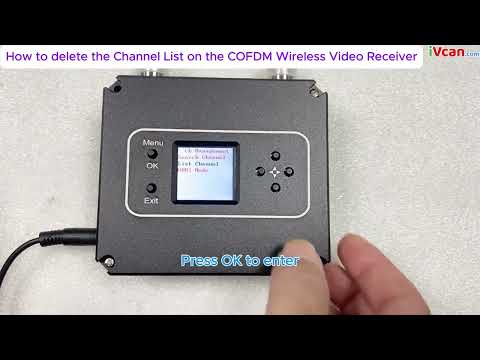
Turn on the power of the receiver and press the “MENU/OK” button to enter the menu. The menu with adjustable parameters is first displayed. If you want to search for a specified frequency, press the “MENU/OK” button to enter the menu. If you need to remove a channel, press the down button to select “ListanbulChannel”, and then press the “MENU/OK” button to enter the menu operation; if you need to save the current channel, press “MENU/OK” at the same time and right-click to confirm the save.


The frequency search method is as follows. After entering the frequency setting menu, the interface is displayed as shown in the figure. Press the left or right button to move the cursor, press the up or down button to adjust the frequency, radio frequency bandwidth, and secret key that match the transmitter. Press “MENU” /OK” key to search. Note that the transmitter must be turned on at this time, otherwise the receiver will not be able to lock because it cannot search for signals.


When the search is completed, press “MENU/OK” to confirm. At this time, the channel is saved in the parameter adjustment board register, as shown in the figure. If you need to save the channel to the receiver register, press the “MENU/OK” key and the right key at the same time.

After the receiver parameter setting is completed, the panel button functions are as follows:
“↑”“↓“: Each individually selectable receiver channel “CH **”
“←”“→”: You can choose to view the hidden parameters of the receiver
“EXIT”: start and stop recording
Micro COFDM Video Transmitter and Receiver Typical troubleshooting
| Fault phenomenon | Solution |
| No image, no sound | 1. Check whether the transmitter battery is charged and whether the transmitter indicator light is normal. Pay special attention to the distance and wiring pattern of the transmitter video cable and power cable from the antenna. 2. Check whether the camera battery is charged, whether the audio and video cable has been connected to the transmitter, and whether the camera is in standby mode. 3. Check whether the receiver antenna is connected properly and whether the antenna connector is wet or loose. 4. Check whether the monitor audio and video cables are connected properly and whether the startup screen is normal. 5. Check the frequency settings, and whether the frequency settings for transmitting and receiving are the same. 6. Check the electromagnetic environment to see if there is interference from same-frequency signals nearby |
| The receiver has no picture, but the sound is normal | 1. Check whether the video cables of the camera and transmitter are connected properly 2. Check whether the video cable between the receiver and the PC is properly connected |
| No sound or noise from the receiver but the normal picture | 1. Check whether the audio cables of the camera and transmitter are connected properly. 2. Check whether the audio cable between the receiver and the TV or audio output device is properly connected. |
| The image is continuous, then pauses, and a black screen appears. | 1. The signal is not good, which is normal. 2. Whether the signal quality display on the LCD screen on the receiver keyboard is normal, and whether the parameter value fluctuates greatly (more than 10). If so, it means there is some frequency interference. |
| Coverage suddenly becomes smaller | 1. Check whether the transmitting antenna and receiving antenna are connected properly and whether there is water or poor contact 2. Check whether the power supply voltage of the transmitter is normal. 3. Check the surrounding environment for electromagnetic interference from signals of the same frequency. |
| The coverage is small and the transmission distance is not far enough | Check the installation position of the receiving antenna, increase the height of the receiving antenna, and use high-gain omnidirectional and directional antennas and diversity reception if necessary |
| There is image and sound, but the image is blurry | Check whether the camera at the front end of the transmitter is focused accurately and whether the autofocus function setting is turned on. |
Video Operation Guide
How to delete the Channel List on the COFDM Wireless Video Receiver
[VF-202408]
Ask A Question
Thank you for your response. ✨