


Diversity two RF demodulator tuner MPEG-TS output double antenna DiBcom chip DVB-T COFDM receiver RX module

Table of Contents
Feature
- Dual antenna reception, SMA antenna interface
- Receiving frequency band: 160MHz~860MHz
- Single channel receiving sensitivity: -97±1dbm at QPSK 8MHz, -98±1dbm at QPSK 6MHz, the sensitivity increases by 3dbm when receiving with dual antennas
- Support high-speed mobile reception
- Supported parameters:
- IFFT:2K,8K
- Guard interval: 1/4, 1/8, 1/16, 1/32
- FEC:1/2, 2/3, 3/4, 5/6, 7/8
- Modulation mapping: QPSK, QAM16, QAM64
- Bandwidth: 1.8MHz~8MHz, step 0.1MHz
- The demodulated digital signal output interface is J3 interface (TSI)
- Power indicator light, work indicator light
- PCBA weight: 13.4 grams
- Board size: 51mm x 30mm
Note
This demodulation module is pure hardware and does not contain an MCU, so it cannot run independently. It can be used as a plug-in module to output TS streams. You need to design it yourself or use our baseboard to work.
This is a dual antenna receiver that outputs TS stream (physical interface). There is no MCU on the module and it cannot be used alone. Customers buy this module and integrate it into their own products, and they also need to transplant the driver into their own products.
This module itself does not have code and cannot be used alone. An external chip is required to load the firmware into it (similar to the early WiFi modules)
J3 Pin interface defines
The J3 interface is a 2×10 20pin 1.27mm pitch straight pin header, which is used to connect our module and the decoder board. It uses TSI to transmit data. Its signal definition is shown in the table below:
| PIN serial number | direction | signal name | describe |
| 1 | IN/OUT | HOST_BUS0 | DR2C I2C Data |
| 2 | IN/OUT | HOST_BUS1 | DR2C I2C Clock |
| 3 | In | RESET_IN | DR2C Reset |
| 4 | PWR | GND | signal place |
| 5 | PWR | VDD_5V | DR2C 5V power input |
| 6 | OUT | HOST_BUS2 | TSI Data0 |
| 7 | OUT | HOST_BUS3 | TSI Data1 |
| 8 | OUT | HOST_BUS4 | TSI Data2 |
| 9 | OUT | HOST_BUS5 | TSI Data3 |
| 10 | OUT | HOST_BUS6 | TSI Data4 |
| 11 | OUT | HOST_BUS7 | TSI Data5 |
| 12 | OUT | HOST_BUS8 | TSI Data6 |
| 13 | OUT | HOST_BUS9 | TSI Data 7 |
| 14 | OUT | HOST_BUS10 | TSI Frame Indicator |
| 15 | OUT | HOST_BUS11 | TSI Sync |
| 16 | OUT | INT_SELECT1 | DR2C mode Select |
| 17 | OUT | HOST_BUS12 | TSI Clock |
| 18 | IN | HOST_BUS13 | FEC Fail |
| 19 | PWR | VDD_3P3V | DR2C 3.3V power input |
| 20 | PWR | GND | signal place |
Module Mechanical Dimensions

Demodulator + Decoder board

FAQ:
Q1: Is the TS output of your demodulation chip serial or parallel?
A1: Parallel.
Q2: Does your module support TS output?
A2: Yes. This module J3 contains an output physical interface.
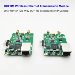
If you need to match it with our decoding baseboard, it not only has HDMI and CVBS output, but also contains an Ethernet port. This Ethernet port supports the output of TS video streams, which can be played on Windows or Linux through VLC player.

Q3: Can I buy a sample of this diversity RF DVB-T demodulator with TS output interface module?
A3: We are happy to provide you with samples. We have to remind you that this is a pure hardware product. In addition to two RF inputs and a J3 interface, there is no separate power supply and video output port, and there is no MCU and firmware on this module, so it cannot be run and tested alone.
If you need to test, please purchase it together with its baseboard (power supply, decoding chip and HDMI/CVBS/Ethernet output). See the picture above. When you understand its performance, you can develop your hardware or peripheral circuits, or we are also happy to provide technical support.
Q4: Can you provide me with the source code and driver? I need to program it.
A4: We need to consider your project requirements and purchase volume before we can provide code and source programs. We are happy to cooperate with you.
Q5: Can the DiBcom handle higher-frequency inputs? The 2.0-2.9 GHz frequency band is available to me.
A: DiBcom 9090MA only supports 170-860Mhz. Please use frequency down conversion to support 2~2.9Ghz.
More About this product
The DiBcom 9090MA is a chipset designed for DVB-T (Digital Video Broadcasting – Terrestrial) reception. It is commonly used in USB TV tuners, automotive applications, and embedded systems. Here’s a detailed overview of its features and setup, particularly for handling TS (Transport Stream) output.
DiBcom 9090MA Overview
-
Core Features:
- DVB-T Support: Compliant with the DVB-T standard.
- High Sensitivity: Optimized for reliable reception, even in challenging environments.
- Diversity Reception: Supports antenna diversity for better signal quality.
- Transport Stream (TS) Output:
- Delivers MPEG-2 TS over a variety of interfaces.
-
Interfaces:
- I2C Interface: For control and configuration.
- TS Output:
- Parallel TS or serial TS modes, selectable based on the application.
- Outputs MPEG-2 TS for decoding or further processing.
-
Applications:
- Wireless COFDM Video receiver
- USB DVB-T tuners for PCs and embedded systems.
- Automotive DVB-T receivers.
- Digital TV integration in portable devices.
Transport Stream (TS) Output
The DiBcom 9090MA outputs MPEG-2 Transport Streams, which is the standard for digital TV broadcasting. Here’s how it works:
-
TS Data Format:TS
- Comprises packets of 188 bytes.
- Contains video, audio, and metadata multiplexed into a single stream.
-
TS Output Modes:
- Parallel TS:
- Outputs 8 bits of data per clock cycle.
- Requires more pins but provides faster data transfer.
- Serial TS:
- Outputs 1 bit per clock cycle.
- Uses fewer pins but may be slower.
- Parallel TS:
-
Clock Signal:
- The chipset provides a clock signal to synchronize the TS data output.
-
Control Signals:
- Data Valid (DVALID): Indicates valid data on the TS bus.
- Sync: Signals the start of a TS packet.
DiBcom and TS output Integration Steps
-
Hardware Connection:
- Connect the TS output pins (parallel or serial) to a demultiplexer or decoder.
- Use an I2C interface to configure the tuner.
-
Configuration via I2C:
- The 9090MA needs to be configured through I2C commands for:9090MA
- Channel frequency.
- Bandwidth (6, 7, or 8 MHz).
- TS output mode (parallel or serial).
- The 9090MA needs to be configured through I2C commands for:9090MA
-
TS Decoding:
- Feed the TS output to a compatible decoder, such as an MPEG-2 decoder or software-based solution.
-
Software Integration:
- Use Linux DVB APIs (if applicable) for capturing and processing TS data.
- Applications like VLC Media Player or custom software can decode and display the TS.
Use Cases
- USB DVB-T Tuners:USB DVB-T:
- Combine with a USB interface IC (e.g., Cypress EZ-USB) for PC-based TV tuners.
- Automotive Receivers:
- Use diversity reception with two or more 9090MA chips for stable reception in moving vehicles.
- Embedded Systems:
- Integrate with ARM-based boards to provide DVB-T functionality in custom devices.
Example Application Circuit
-
Components:
- DiBcom 9090MA as the tuner chip.
- A RF front-end for antenna and signal conditioning.
- I2C interface connected to a microcontroller or CPU.
- TS output connected to a decoder or USB bridge.
-
TS Output Example:
- Parallel Mode:
- Data lines: TS[7:0].
- Control lines: CLK, DVALID, and SYNC.
- Serial Mode:
- Single data line: TS_DATA.
- Clock and control lines.
- Parallel Mode:


Darshanand Sugrim –
If you need a dependable and versatile RF demodulator with diversity support, this is the one