


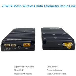
Mô-đun vô tuyến mạng lưới IP cho máy bay không người lái bầy đàn
 Đặc tính
Các 1999 Mô-đun vô tuyến mạng lưới IP thực hiện liên lạc đường dài không có trung tâm giữa các nút quy mô lớn.
Tất cả các nút có thể giao tiếp độc lập mà không can thiệp lẫn nhau. Nó giải quyết các vấn đề truy cập kênh dày đặc quy mô lớn, Truyền không dây, mạng năng động, và các cụm không người lái.
Cần có các vấn đề kỹ thuật như tổ chức lại linh hoạt và cộng tác theo thời gian thực để nhận ra rằng mạng bầy đàn có khả năng kết nối mạng của hành vi giống như bầy đàn sinh học., mạng tự trị theo kịch bản, tổ chức lại linh hoạt và khả năng cộng tác thông minh.
Các 1999 Mô-đun vô tuyến mạng lưới IP có các tính năng dưới đây:
khả năng truy cập nút quy mô lớn dung lượng lớn;
16-khả năng phủ sóng mạng tự tổ chức của hop;
độ trễ cực thấp;
đơn giản và dễ sử dụng
Các 1999 Mô-đun vô tuyến mạng lưới IP có thể được sử dụng cho máy bay không người lái, Internet vạn vật, liên kết dữ liệu, điều khiển từ xa, Các kịch bản ứng dụng như thu thập dữ liệu, trí tuệ nhân tạo, và trang bị cá nhân của người lính.
Đặc điểm kỹ thuật
- Dải tần số: 825MHz~850 MHz hoặc 902~928 MHz
- RF băng thông: 1MHz/500kHz/250kHz/125kHz
- Tốc độ dữ liệu giao diện vô tuyến: tối đa 740kbps@1MHz, 370kbps@500kHz, 185kbps@250kHz, 92kbps@125kHz
- Số nút được hỗ trợ: tối đa 1024
- Số bước nhảy mạng: tối đa 16 hoa bia.
- Giao tiếp đa tác vụ đầy đủ: ủng hộ;
- Khoảng cách nhìn thấy được: ≥30 km;
- đặc biệt không có trung tâm (lưới thép) mạng: Hỗ trợ mạng ad hoc không trung tâm, và sự hư hỏng của bất kỳ nút nào trong mạng sẽ không ảnh hưởng đến việc liên lạc;
- Nhảy tần số: hỗ trợ không nhảy tần và nhảy tần, tần số tối đa tốc độ nhảy là 1800 lần mỗi giây
- Mạng tự tổ chức phi trung tâm: Hỗ trợ mạng tự tổ chức không trung tâm. Sự hư hỏng của bất kỳ nút nào trong mạng sẽ không ảnh hưởng đến việc liên lạc.
- Thời gian thiết lập mạng: ở trong 1 thứ hai
- Độ trễ truyền từ đầu đến cuối: tối thiểu 2 mili giây
- Cấu trúc liên kết động: Hỗ trợ cấu trúc liên kết động, hỗ trợ các nút tham gia và rời đi, và có thể liên lạc bình thường ngay cả khi cấu trúc liên kết mạng thay đổi hoặc biến dạng.
- Tự duy trì thời gian: mạng có thể được xây dựng mà không cần thời gian bên ngoài
- Công suất truyền tải: 0.5W (có thể được kết nối với bộ khuếch đại công suất cao bên ngoài)
- Nhận độ nhạy: -114dBm@125kHz, -111dBm@250kHz, -108dBm@500kHz, -105dBm@1 MHz
- Sự tiêu thụ ít điện năng: Điện năng tiêu thụ ít hơn 1 watt khi nhận và ít hơn 5 watt khi truyền.
- Độ ổn định tần số: 1ppm
- Encryption: Mã hóa AES128-bit
- điện áp làm việc: 3.6~5V
- Nhiệt độ hoạt động: -30~+75oC
- trọng lượng mô-đun: <45g
Thông số làm việc
| tham số | điều kiện | nhỏ nhất | đặc trưng | tối đa | đơn vị |
| tần số làm việc | 825 | 850 | MHz | ||
| Nhiệt độ hoạt động | -30 | 25 | +75 | ℃ | |
| Điện áp hoạt động | 3.6 | 4.2 | 5 | TRONG | |
| Truyền điện | @VCC=5V | 26 | 27 | 28 | dBm |
| nhận nhạy cảm | 125kHz | -116 | -114 | -112 | dBm |
| 250kHz | -113 | -111 | -109 | ||
| 500kHz | -110 | -108 | -106 | ||
| 1MHz | -107 | -105 | -103 | ||
| Công suất đầu vào RF tối đa | +10 | dBm | |||
| Giấc ngủ hiện tại | @EN=0 | 40 | uA | ||
| nhận được hiện tại | 200 | 240 | mA | ||
| Dòng phát xạ | @VCC=5V,0.5W | 1000 | 1200 | mA |
※Ghi chú:Nếu điều kiện làm việc của mô-đun vượt quá giá trị giới hạn trên, nó có thể gây ra hư hỏng vĩnh viễn cho mô-đun.
Đầu nối mô-đun vô tuyến mạng lưới IP

| số seri | Tên giao diện | Định nghĩa giao diện | chú ý |
| 1 | Giao diện nguồn | Nguồn điện tích cực | XT30PW-M, nguồn điện 5V-28V bên ngoài hoặc pin. |
| Cung cấp điện tiêu cực | |||
| 2 | Kiểm soát chế độ | C | chế độ cấu hình |
| D | Chế độ truyền dữ liệu trong suốt | ||
| 3 | giao diện dữ liệu | 3.3sản lượng điện V | Tải ≦150mA |
| Cổng nối tiếp Tx (B) | Hỗ trợ mức TTL3.3V, Cấp độ RS232, Mức RS485. Trao đổi trước trước khi đặt hàng. | ||
| Cổng nối tiếp Rx (Một) | |||
| đất | nơi dữ liệu | ||
| Chế độ0 | Đối với các chân cấu hình chế độ làm việc, vui lòng tham khảo bảng thông số kỹ thuật. | ||
| ACK | Tín hiệu chỉ báo trạng thái cấu hình mô-đun. | ||
| 4 | Chỉ báo trạng thái | Đèn báo nguồn PWR | Sáng lên khi có nguồn vào. |
| Đèn báo truyền TX | Đèn tự kiểm tra khi bật nguồn sáng lên trong giây lát, và đèn báo sáng lên khi dữ liệu đang được truyền đi. | ||
| Đèn báo nhận RX | Đèn tự kiểm tra khi bật nguồn sáng lên trong giây lát, và đèn báo sáng lên khi nhận được dữ liệu. | ||
| Đèn báo nhiễu CA | Nó sáng lên một thời gian ngắn trong quá trình tự kiểm tra khi bật nguồn và vẫn sáng ở chế độ cấu hình. Ở chế độ truyền trong suốt:
Khi đèn sáng, nó có nghĩa là có sự can thiệp vào giao diện không khí. Ánh sáng càng sáng, sự can thiệp càng mạnh. |
||
| Chỉ báo bộ đệm dữ liệu FU | Sáng lên khi bộ đệm dữ liệu đầy. | ||
| Chỉ báo bộ đệm dữ liệu HFU | Sáng lên khi bộ đệm dữ liệu đầy một nửa. | ||
| 5 | Đầu ra RF | giao diện đầu ra RF | SMA-K, |
Chân mô-đun lõi và định nghĩa

| viết tắt | mô tả |
| TỪ | Đầu vào kỹ thuật số |
| LÀM | Đầu ra kỹ thuật số |
| PHẦN | Đầu vào hoặc đầu ra kỹ thuật số |
| P | Quyền lực |
| G | Đất |
bảng định nghĩa chân cắm
| Ghim KHÔNG | Tên ghim① | Kiểu | Sự miêu tả |
| 1 | RF_TR0 | LÀM | Gửi và nhận tín hiệu chỉ báo, mức độ thấp đang truyền, cấp cao đang nhận được (công tắc tần số vô tuyến điều khiển bên ngoài) |
| 2 | RF_TR1 | LÀM | Gửi và nhận tín hiệu chỉ báo, mức cao đang truyền, mức độ thấp đang nhận được (công tắc tần số vô tuyến điều khiển bên ngoài hoặc đèn chỉ báo LED cho biết có truyền dữ liệu trên giao diện vô tuyến) |
| 3 | RF_TXON | LÀM | Tín hiệu kích hoạt bộ khuếch đại công suất, mức độ thấp có nghĩa là tắt, mức cao có nghĩa là bật (bộ khuếch đại công suất điều khiển bên ngoài) |
| 4 | RF_RXON | LÀM | Tín hiệu kích hoạt bộ khuếch đại tiếng ồn thấp, mức độ thấp có nghĩa là tắt, mức cao có nghĩa là bật (bộ khuếch đại tiếng ồn thấp được điều khiển bên ngoài) |
| 5 | CARRIER_S | LÀM | Tín hiệu chỉ báo nghe khung sóng mang CARRIER_SENSE, mức cao nghĩa là có sóng mang trên giao diện vô tuyến, và đèn chỉ báo LED bên ngoài có thể được kết nối để cho biết rằng có sự tiếp nhận dữ liệu trên giao diện vô tuyến. |
| 6 | ACK | LÀM | Tín hiệu chỉ báo trạng thái cấu hình mô-đun, mức cao có nghĩa là cấu hình đã hoàn tất, mức thấp có nghĩa là cấu hình đang được tiến hành |
| 7 | TRONG③ | TỪ | Mô-đun bật tín hiệu kích hoạt, mô-đun cấp thấp bị tắt, mô-đun cấp cao hoặc nổi được bật |
| 8 | MODE0 | TỪ | Tín hiệu lựa chọn chế độ làm việc của mô-đun, Mô tả chức năng cụ thể được thể hiện trong Bảng 6 |
| 9 | CHẾ ĐỘ1 | TỪ | |
| 10 | GND | G | GND |
| 11 | UART_RXD | TỪ | Chân nhận cổng nối tiếp mô-đun |
| 12 | UART_TXD | LÀM | Chân máy phát cổng nối tiếp mô-đun |
| 13 | HALF_FULL | LÀM | Tín hiệu chỉ báo bộ đệm dữ liệu mô-đun, mức cao có nghĩa là bộ đệm dữ liệu đã đầy một nửa |
| 14 | ĐẦY | LÀM | Tín hiệu chỉ báo bộ đệm dữ liệu mô-đun, mức cao có nghĩa là bộ đệm dữ liệu đã đầy |
| 15 | GND | G | GND |
| 16 | JTAG_TCK | TỪ | Chân lập trình mô-đun② |
| 17 | JTAG_TDI | TỪ | |
| 18 | JTAG_TDO | LÀM | |
| 19 | JTAG _TMS | TỪ | |
| 20 | JTAG _TRST | TỪ | |
| 21 | GND | G | GND |
| 22 | GND | G | GND |
| 23 | VCC | P | Pin hoặc nguồn điện ngoài 3.6V~5V |
| 24 | VCC | P | Pin hoặc nguồn điện ngoài 3.6V~5V |
| 25 | TRÊN | AIO | Chân đầu vào/đầu ra tín hiệu RF, được kết nối với ăng-ten 50Ω bên ngoài hoặc đầu cuối RF bên ngoài, tùy chọn kết nối với IPEX 1. |
| 26 | GND | G | GND |
chú thích:
- Mô-đun được điều chỉnh nội bộ bởi 3,3V LDO, và tất cả các IO kỹ thuật số đều ở 3.3 cấp độ LVTTL;
- Để thuận tiện cho việc nâng cấp phần mềm tiếp theo, nên dẫn các chân lập trình mô-đun ra ngoài bằng các đầu cắm hoặc đầu nối chân cắm;
- Chân EN không thể kết nối trực tiếp với nguồn điện. Nếu nó cần được kết nối với nguồn điện, phải thêm một điện trở giới hạn dòng điện hoặc phải sử dụng công tắc điều khiển mức LVTTL 3,3V;


yakov –
Mô-đun vô tuyến dạng lưới IP này là một bước đột phá cho các hoạt động của máy bay không người lái bầy đàn! Mạng tự phục hồi của nó duy trì liên lạc hoàn hảo trên khắp 50+ máy bay không người lái trong nhiệm vụ tìm kiếm rừng của chúng tôi, ngay cả khi chướng ngại vật chặn các liên kết trực tiếp. Độ trễ gần như bằng 0 và đồng bộ hóa nút tự động giữ cho đội hình luôn hoạt động ở tốc độ 60 mph, trong khi mã hóa cấp quân sự đảm bảo tính toàn vẹn dữ liệu. Thiết lập là plug-and-play—không cần mã hóa phức tạp—và khả năng nhảy tần thích ứng loại bỏ nhiễu RF đô thị một cách dễ dàng. Dành cho các đội ứng phó thảm họa và các chương trình biểu diễn ánh sáng trên không đòi hỏi trí thông minh bầy đàn vững chắc, mô-đun này mang lại khả năng kết nối chống đạn gần như có khả năng ngoại cảm. Tương lai của máy bay không người lái hợp tác là đây!