


用於集群無人機的 IP 網狀網路無線電模組
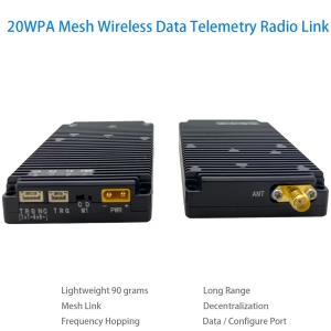
 特徵
特徵
該 1999 IP mesh network radio module realizes centerless long-distance communication between large-scale nodes.
All nodes can communicate independently without interfering with each other. It solves the problems of large-scale dense channel access, 無線傳輸, dynamic networking, and unmanned clusters.
Technical problems such as flexible reorganization and real-time collaboration are required to realize that the swarm network has the networking capability of biological swarm-like behavior, scenario-driven autonomous networking, flexible reorganization and intelligent collaboration capabilities.
該 1999 IP mesh network radio module has below features:
large-capacity large-scale node access capabilities;
16-hop self-organizing network coverage capabilities;
超低延遲;
simple and easy to use
該 1999 IP mesh network radio module can be used for swarm drones, Internet of Things, data links, 遙控, Application scenarios such as data collection, artificial intelligence, and individual soldier equipment.
規範
- 頻率範圍: 825MHz~850MHz or 902~928Mhz
- 射頻頻寬: 1MHz/500kHz/250kHz/125kHz
- Air interface data rate: maximum 740kbps@1MHz, 370kbps@500kHz, 185kbps@250kHz, 92kbps@125kHz
- Supported number of nodes: 最大限度 1024
- Number of network hops: 最大限度 16 啤酒花.
- Full multi-tasking communication: 支援;
- Visible distance: ≥30 kilometers;
- Centerless ad hoc (網) 網路: Supports centerless ad hoc network, and the damage of any node in the network will not affect communication;
- Frequency hopping: supports no frequency hopping and frequency hopping, the maximum frequency hopping speed is 1800 times per second
- Centerless self-organizing network: Supports centerless self-organizing network. The damage of any node in the network will not affect the communication.
- Network establishment time: 之內 1 第二
- End-to-end transmission delay: minimum 2ms
- Dynamic topology: Supports dynamic topology, supports nodes joining and leaving, and can communicate normally even if the network topology changes or deforms.
- Time self-sustaining: the network can be built without external timing
- 發射功率: 0.5W¯¯ (can be connected to an external high-power amplifier)
- 接收靈敏度: -114dBm@125kHz, -111dBm@250kHz, -108dBm@500kHz, -105dBm@1MHz
- 低功耗: The power consumption is less than 1 watts when receiving and less than 5 watts when transmitting.
- Frequency stability: ≤1ppm
- 加密: AES128位元加密
- Operating voltage: 3.6~5V
- 工作溫度: -30~+75℃
- Module weight: <45G
Working parameters
| 範圍 | condition | smallest | typical | 最大限度 | unit |
| 工作頻率 | 825 | 850 | 兆赫 | ||
| 工作溫度 | -30 | 25 | +75 | ℃ | |
| 工作電壓 | 3.6 | 4.2 | 5 | 在 | |
| 發射功率 | @VCC=5V | 26 | 27 | 28 | dBm的 |
| 接收靈敏度 | 125千赫 | -116 | -114 | -112 | dBm的 |
| 250千赫 | -113 | -111 | -109 | ||
| 500千赫 | -110 | -108 | -106 | ||
| 1兆赫 | -107 | -105 | -103 | ||
| Maximum RF input power | +10 | dBm的 | |||
| Sleep current | @EN=0 | 40 | 微安 | ||
| receive current | 200 | 240 | 毫安 | ||
| Emission current | @VCC=5V,0.5W¯¯ | 1000 | 1200 | 毫安 |
※Note:If the working conditions of the module exceed the above limit values, it may cause permanent damage to the module.
IP mesh network radio module connector

| 序號 | Interface name | 介面定義 | 評論 |
| 1 | 電源介面 | Power supply positive | XT30PW-M, external 5V-28V power supply or battery. |
| Negative power supply | |||
| 2 | Mode control | C | configuration mode |
| D | Data transparent transmission mode | ||
| 3 | 資料介面 | 3.3電源輸出電壓 | Load ≦150mA |
| Serial port Tx (乙) | Support TTL3.3V level, RS232電平, RS485 level. Communicate in advance before placing an order. | ||
| Serial port Rx (一個) | |||
| land | data place | ||
| Mode0 | For working mode configuration pins, please refer to the specification sheet. | ||
| ACK | Module configuration status indication signal. | ||
| 4 | 狀態指示燈 | PWR power indicator light | Lights up when power is input. |
| TX transmit indicator light | The power-on self-test lights up briefly, and the indicator light lights up when data is being transmitted. | ||
| RX receiving indicator light | The power-on self-test lights up briefly, and the indicator light lights up when data is received. | ||
| CA interference indicator light | It lights up briefly during power-on self-test and stays on in configuration mode. In transparent transmission mode:
當燈亮時, it means there is interference on the air interface. The brighter the light, the stronger the interference. |
||
| FU data cache indicator | Lights up when the data cache is full. | ||
| HFU data cache indicator | Lights up when the data cache is half full. | ||
| 5 | 射頻輸出 | RF output interface | SMA-K, |
Core module pins and definitions

| 縮寫 | describe |
| FROM | 數位輸入 |
| 做 | 數位輸出 |
| PART | Digital input or output |
| P | 功率 |
| G | 地面 |
pin definition table
| 腳位號 | 引腳名稱① | 類型 | 描述 |
| 1 | RF_TR0 | 做 | Send and receive indicator signals, low level is transmitting, high level is receiving (external control radio frequency switch) |
| 2 | RF_TR1 | 做 | Send and receive indicator signals, high level is transmitting, low level is receiving (external control radio frequency switch or LED indicator light indicates that there is data transmission on the air interface) |
| 3 | RF_TXON | 做 | Power amplifier enable signal, low level means off, high level means on (external control power amplifier) |
| 4 | RF_RXON | 做 | Low-noise amplifier enable signal, low level means off, high level means on (externally controlled low-noise amplifier) |
| 5 | CARRIER_S | 做 | CARRIER_SENSE carrier frame listening indication signal, high level means there is a carrier on the air interface, and an external LED indicator light can be connected to indicate that there is data reception on the air interface. |
| 6 | ACK | 做 | Module configuration status indication signal, high level means configuration is completed, low level means configuration is in progress |
| 7 | 在③ | FROM | Module turn on enable signal, low level module is turned off, high level or floating module is turned on |
| 8 | MODE0 | FROM | Module working mode selection signal, specific function description is shown in Table 6 |
| 9 | MODE1 | FROM | |
| 10 | 接地 | G | 接地 |
| 11 | UART_RXD | FROM | Module serial port receiving pin |
| 12 | UART_TXD | 做 | Module serial port transmitter pin |
| 13 | HALF_FULL | 做 | Module data cache indication signal, high level means the data cache is half full |
| 14 | FULL | 做 | Module data cache indication signal, high level means the data cache is full |
| 15 | 接地 | G | 接地 |
| 16 | JTAG_TCK | FROM | Module programming pin② |
| 17 | JTAG_TDI | FROM | |
| 18 | JTAG _TDO | 做 | |
| 19 | JTAG _TMS | FROM | |
| 20 | JTAG _TRST | FROM | |
| 21 | 接地 | G | 接地 |
| 22 | 接地 | G | 接地 |
| 23 | VCC | P | External 3.6V~5V battery or power supply |
| 24 | VCC | P | External 3.6V~5V battery or power supply |
| 25 | 在 | 一體機 | RF signal input/output pin, connected to an external 50Ω antenna or external RF front-end, optionally connected to IPEX 1. |
| 26 | 接地 | G | 接地 |
注意:
- The module is internally regulated by 3.3V LDO, and all digital IOs are at 3.3 LVTTL level;
- In order to facilitate subsequent software upgrades, it is recommended to lead out the module programming pins with pin headers or connectors;
- The EN pin cannot be directly connected to the power supply. If it needs to be connected to the power supply, a current limiting resistor must be added or a 3.3V LVTTL level control switch must be used;


Yakov –
This IP mesh radio module is a breakthrough for swarm drone operations! Its self-healing network maintained flawless communication across 50+ drones during our forest search mission, even when obstacles blocked direct links. The near-zero latency and automatic node synchronization kept formations tight at 60mph, while the military-grade encryption ensured data integrity. Setup was plug-and-play—no complex coding needed—and the adaptive frequency hopping shrugged off urban RF interference effortlessly. For disaster response teams and aerial light shows demanding rock-solid swarm intelligence, this module delivers bulletproof connectivity that feels almost telepathic. The future of collaborative drones is here!