


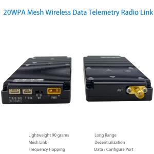
Moduł radiowy sieci IP mesh dla dronów roju
 Cecha
Cecha
Plik 1999 Moduł radiowy sieci IP mesh realizuje bezcentralną komunikację na duże odległości pomiędzy dużymi węzłami.
Wszystkie węzły mogą komunikować się niezależnie, nie zakłócając się nawzajem. Rozwiązuje problemy dostępu do gęstych kanałów na dużą skalę, transmisja bezprzewodowa, dynamiczna sieć, i bezzałogowe klastry.
Aby zdać sobie sprawę, że sieć roju ma zdolność tworzenia sieci o biologicznym zachowaniu podobnym do roju, wymagane są problemy techniczne, takie jak elastyczna reorganizacja i współpraca w czasie rzeczywistym, sieci autonomiczne oparte na scenariuszach, elastyczna reorganizacja i inteligentne możliwości współpracy.
Plik 1999 Moduł radiowy sieci IP mesh ma poniższe funkcje:
możliwości dostępu do węzłów na dużą skalę o dużej pojemności;
16-przeskocz, samoorganizujące się możliwości pokrycia sieci;
bardzo niskie opóźnienia;
prosty i łatwy w użyciu
Plik 1999 Moduł radiowy sieci IP mesh może być stosowany w dronach roju, Internet przedmiotów, łącza danych, pilot, Scenariusze zastosowań, takie jak zbieranie danych, sztuczna inteligencja, oraz indywidualne wyposażenie żołnierza.
Specyfikacja
- Zakres częstotliwości: 825MHz ~ 850 MHz lub 902 ~ 928 MHz
- RF Bandwidth: 1MHz/500 kHz/250 kHz/125 kHz
- Szybkość transmisji danych interfejsu radiowego: maksymalnie 740 kb/s przy 1 MHz, 370kbps przy 500 kHz, 185kbps przy 250 kHz, 92kbps przy 125 kHz
- Obsługiwana liczba węzłów: maksymalny 1024
- Liczba przeskoków sieciowych: maksymalny 16 chmiel.
- Pełna wielozadaniowa komunikacja: wsparcie;
- Widoczna odległość: ≥30 kilometrów;
- Bezcentryczne ad hoc (siatka) sieć: Obsługuje bezcentralną sieć ad hoc, a uszkodzenie dowolnego węzła w sieci nie będzie miało wpływu na komunikację;
- Skakanie po częstotliwościach: nie obsługuje przeskakiwania częstotliwości i przeskakiwania częstotliwości, maksymalna częstotliwość prędkość skakania jest 1800 razy na sekundę
- Bezcentralna, samoorganizująca się sieć: Obsługuje bezcentrową, samoorganizującą się sieć. Uszkodzenie dowolnego węzła w sieci nie będzie miało wpływu na komunikację.
- Czas założenia sieci: w 1 druga
- Opóźnienie transmisji od końca do końca: minimum 2 ms
- Topologia dynamiczna: Obsługuje topologię dynamiczną, obsługuje łączenie i opuszczanie węzłów, i może komunikować się normalnie, nawet jeśli topologia sieci ulegnie zmianie lub odkształceniu.
- Czas samowystarczalny: sieć można zbudować bez zewnętrznego taktowania
- Moc transmisji: 0.5W (można podłączyć do zewnętrznego wzmacniacza dużej mocy)
- Odbieranie wrażliwości: -114dBm przy 125 kHz, -111dBm przy 250 kHz, -108dBm przy 500 kHz, -105dBm przy 1 MHz
- Niskie zużycie energii: Zużycie energii jest mniejsze niż 1 watów podczas odbioru i mniej niż 5 watów podczas transmisji.
- Stabilność częstotliwości: ≤1 ppm
- Szyfrowanie: Szyfrowanie AES128-bitowe
- napięcie robocze: 3.6~5 V
- Temperatura robocza: -30~+75 ℃
- moduł wagowy: <45sol
Parametry pracy
| parametr | stan | najmniejszy | typowy | maksymalny | jednostka |
| częstotliwość pracy | 825 | 850 | MHz | ||
| Temperatura robocza | -30 | 25 | +75 | ℃ | |
| Napięcie pracy | 3.6 | 4.2 | 5 | W | |
| Moc nadawania | @VCC=5V | 26 | 27 | 28 | dBm |
| otrzymuj czułość | 125kHz | -116 | -114 | -112 | dBm |
| 250kHz | -113 | -111 | -109 | ||
| 500kHz | -110 | -108 | -106 | ||
| 1MHz | -107 | -105 | -103 | ||
| Maksymalna moc wejściowa RF | +10 | dBm | |||
| Prąd uśpienia | @EN=0 | 40 | uA | ||
| odbierać prąd | 200 | 240 | mA | ||
| Prąd emisji | @VCC=5V,0.5W | 1000 | 1200 | mA |
※Notatka:Jeżeli warunki pracy modułu przekraczają powyższe wartości graniczne, może to spowodować trwałe uszkodzenie modułu.
Złącze modułu radiowego sieci IP mesh

| numer seryjny | Nazwa interfejsu | Definicja interfejsu | Uwaga |
| 1 | Interfejs zasilania | Zasilanie dodatnie | XT30PW-M, zewnętrzny zasilacz 5V-28V lub akumulator. |
| Ujemne zasilanie | |||
| 2 | Kontrola trybu | do | tryb konfiguracji |
| re | Tryb transmisji danych przezroczysty | ||
| 3 | interfejs danych | 3.3Moc wyjściowa V | Obciążenie ≦150mA |
| Port szeregowy Tx (b) | Obsługa poziomu TTL3.3V, Poziom RS232, Poziom RS485. Skontaktuj się z wyprzedzeniem przed złożeniem zamówienia. | ||
| Port szeregowy Rx (ZA) | |||
| grunt | miejsce danych | ||
| Tryb0 | Dla pinów konfiguracji trybu pracy, proszę zapoznać się z arkuszem specyfikacji. | ||
| POTWIERDŹ | Sygnał wskazujący stan konfiguracji modułu. | ||
| 4 | Wskaźnik stanu | Kontrolka zasilania PWR | Świeci po podłączeniu zasilania. |
| Kontrolka nadawania TX | Na krótko zapala się autotest po włączeniu zasilania, i lampka kontrolna zapala się, gdy dane są przesyłane. | ||
| Kontrolka odbioru RX | Na krótko zapala się autotest po włączeniu zasilania, a kontrolka zaświeci się, gdy dane zostaną odebrane. | ||
| Kontrolka zakłóceń CA | Zapala się na krótko podczas autotestu po włączeniu zasilania i pozostaje zapalona w trybie konfiguracji. W przezroczystym trybie transmisji:
Kiedy światło jest włączone, oznacza to, że występują zakłócenia na interfejsie radiowym. Im jaśniejsze światło, tym silniejsze zakłócenia. |
||
| Wskaźnik pamięci podręcznej danych FU | Świeci się, gdy pamięć podręczna danych jest pełna. | ||
| Wskaźnik pamięci podręcznej danych HFU | Świeci się, gdy pamięć podręczna danych jest zapełniona w połowie. | ||
| 5 | Wyjście RF | interfejs wyjściowy RF | SMA-K, |
Styki modułu rdzenia i definicje

| skrót | opisać |
| Z | Wejście cyfrowe |
| DO | Wyjście cyfrowe |
| CZĘŚĆ | Wejście lub wyjście cyfrowe |
| P | Moc |
| sol | Grunt |
tabela definicji pinów
| Pin nr | Nazwa pinu① | Rodzaj | Opis |
| 1 | RF_TR0 | DO | Wysyłaj i odbieraj sygnały wskaźnikowe, transmitowany jest niski poziom, wysoki poziom odbiera (zewnętrzny przełącznik częstotliwości radiowej) |
| 2 | RF_TR1 | DO | Wysyłaj i odbieraj sygnały wskaźnikowe, wysoki poziom transmituje, odbierany jest niski poziom (Zewnętrzny przełącznik częstotliwości radiowej lub lampka kontrolna LED wskazują, że odbywa się transmisja danych na interfejsie radiowym) |
| 3 | RF_TXON | DO | Sygnał włączenia wzmacniacza mocy, niski poziom oznacza wyłączenie, wysoki poziom oznacza włączony (zewnętrzny wzmacniacz mocy sterującej) |
| 4 | RF_RXON | DO | Sygnał włączający wzmacniacz o niskim poziomie szumów, niski poziom oznacza wyłączenie, wysoki poziom oznacza włączony (sterowany zewnętrznie wzmacniacz niskoszumowy) |
| 5 | PRZEWOŹNIK_S | DO | CARRIER_SENSE sygnał wskazujący nasłuch ramki nośnej, wysoki poziom oznacza, że na interfejsie radiowym znajduje się nośnik, można także podłączyć zewnętrzną lampkę kontrolną LED, aby wskazać, że na interfejsie radiowym trwa odbiór danych. |
| 6 | POTWIERDŹ | DO | Sygnał wskazujący stan konfiguracji modułu, wysoki poziom oznacza, że konfiguracja została zakończona, niski poziom oznacza, że konfiguracja jest w toku |
| 7 | W③ | Z | Moduł włącza sygnał zezwolenia, moduł niskiego poziomu jest wyłączony, wysoki poziom lub moduł pływający jest włączony |
| 8 | TRYB0 | Z | Sygnał wyboru trybu pracy modułu, szczegółowy opis funkcji przedstawiono w tabeli 6 |
| 9 | TRYB1 | Z | |
| 10 | GND | sol | GND |
| 11 | UART_RXD | Z | Pin odbiorczy portu szeregowego modułu |
| 12 | UART_TXD | DO | Pin nadajnika portu szeregowego modułu |
| 13 | W POŁOWIE PEŁNA | DO | Sygnał wskazujący pamięć podręczną danych modułu, wysoki poziom oznacza, że pamięć podręczna danych jest zapełniona w połowie |
| 14 | PEŁNY | DO | Sygnał wskazujący pamięć podręczną danych modułu, wysoki poziom oznacza, że pamięć podręczna danych jest pełna |
| 15 | GND | sol | GND |
| 16 | JTAG_TCK | Z | Pin do programowania modułu② |
| 17 | JTAG_TDI | Z | |
| 18 | JTAG_TDO | DO | |
| 19 | JTAG_TMS | Z | |
| 20 | JTAG_TRST | Z | |
| 21 | GND | sol | GND |
| 22 | GND | sol | GND |
| 23 | VCC | P | Zewnętrzny akumulator lub zasilacz 3,6 V ~ 5 V |
| 24 | VCC | P | Zewnętrzny akumulator lub zasilacz 3,6 V ~ 5 V |
| 25 | NA | AIO | Pin wejściowy/wyjściowy sygnału RF, podłączony do zewnętrznej anteny 50 Ω lub zewnętrznego interfejsu RF, opcjonalnie podłączony do IPEX 1. |
| 26 | GND | sol | GND |
Uwaga:
- Moduł jest wewnętrznie regulowany napięciem 3,3 V LDO, i wszystkie cyfrowe wejścia/wyjścia są w stanie 3.3 Poziom LVTTL;
- W celu ułatwienia późniejszych aktualizacji oprogramowania, zaleca się wyprowadzenie pinów programujących moduł za pomocą listew pinowych lub złączy;
- Pinu EN nie można podłączyć bezpośrednio do zasilacza. Jeśli konieczne jest podłączenie do źródła zasilania, należy dodać rezystor ograniczający prąd lub zastosować przełącznik kontroli poziomu LVTTL 3,3 V;


Jakov –
Ten moduł radiowy IP Mesh to przełom dla operacji dronów roju! Jego sieć samopomocy utrzymywała bezbłędną komunikację 50+ Drony podczas naszej misji wyszukiwania leśnego, Nawet gdy przeszkody zablokowały bezpośrednie linki. Prawie zerowa opóźnienie i automatyczna synchronizacja węzłów utrzymywały ciasne formacje przy prędkości 60 km / h, podczas gdy szyfrowanie klasy wojskowej zapewniło integralność danych. Konfiguracja była plug-and-play-nie potrzebna złożona kodowanie-a przeskakowanie częstotliwości adaptacyjnej wzruszyło się od zakłóceń miejskich RF. W przypadku zespołów reagowania na katastrofy i światła powietrzne pokazują wymagającą inteligencję rownicową solidną, Ten moduł zapewnia kuloodporną łączność, która wydaje się niemal telepatyczna. Przyszłość wspólnych dronów!