


군집 드론용 IP 메시 네트워크 무선 모듈
 특색
특색
그만큼 1999 IP Mesh Network Radio Module 대규모 노드 간의 중심이없는 장거리 통신을 실현합니다..
모든 노드는 서로 방해하지 않고 독립적으로 통신 할 수 있습니다.. 대규모 조밀 한 채널 액세스 문제를 해결합니다, 무선 전송, 동적 네트워킹, 무인 클러스터.
Swarm 네트워크가 생물학적 떼와 같은 행동의 네트워킹 기능을 가지고 있음을 깨닫기 위해서는 Flexible Reorganization 및 실시간 협업과 같은 기술적 문제가 필요합니다., 시나리오 중심의 자율 네트워킹, 유연한 재구성 및 지능형 협업 기능.
그만큼 1999 IP 메쉬 네트워크 라디오 모듈에는 아래 기능이 있습니다:
대용량 대규모 노드 액세스 기능;
16-홉 자체 구성 네트워크 커버리지 기능;
매우 낮은 대기 시간;
간단하고 사용하기 쉽습니다
그만큼 1999 IP Mesh 네트워크 라디오 모듈은 Swarm Drones에 사용될 수 있습니다., 사물 인터넷, 데이터 링크, 리모콘, 데이터 수집과 같은 응용 프로그램 시나리오, 인공 지능, 그리고 개별 군인 장비.
사양
- 주파수 범위: 825MHz ~ 850MHz 또는 902 ~ 928MHz
- RF 대역폭: 1MHz/500kHz/250kHz/125kHz
- 에어 인터페이스 데이터 속도: 최대 740kbps@1MHz, 370KBPS@500kHz, 185KBPS@250kHz, 92KBPS@125kHz
- 지원되는 노드 수: 최고 1024
- 네트워크 홉 수: 최고 16 홉.
- 완전한 멀티 태스킹 커뮤니케이션: 지원하다;
- 눈에 보이는 거리: ≥30 킬로미터;
- 중심이없는 임시 (망사) 회로망: Centerless Ad Hoc 네트워크를 지원합니다, 그리고 네트워크의 노드의 손상은 통신에 영향을 미치지 않습니다.;
- 주파수 호핑: 주파수 호핑 및 주파수 호핑을 지원하지 않습니다, 최대 주파수 호핑 속도입니다 1800 초당 시간
- 센터리스 자가 조직 네트워크: 중심이없는 자체 조직 네트워크를 지원합니다. 네트워크의 노드 손상은 통신에 영향을 미치지 않습니다..
- 네트워크 설립 시간: 이내에 1 초
- 엔드 투 엔드 전송 지연: 최소 2ms
- 역동적 인 토폴로지: 동적 토폴로지를 지원합니다, 결합 및 떠나는 노드를 지원합니다, 네트워크 토폴로지가 변경되거나 변형 되더라도 정상적으로 통신 할 수 있습니다..
- 시간이 자립적입니다: 네트워크는 외부 타이밍없이 구축 할 수 있습니다
- 전송 전력: 0.5W (외부 고전력 증폭기에 연결할 수 있습니다)
- 수신 감도: -114DBM@125kHz, -111DBM@250kHz, -108DBM@500kHz, -105DBM@1MHz
- 저전력 소비: 전력 소비는보다 적습니다 1 수신 할 때 와트 5 전송시 와트.
- 주파수 안정성: ≤ 1ppm
- 암호화: AES128비트 암호화
- 작동 전압: 3.65V
- 작동 온도: -30~+75 5
- 모듈 무게: <45지
작업 매개 변수
| 매개변수 | 조건 | 작은 | 전형적인 | 최고 | 단위 |
| 작동 주파수 | 825 | 850 | 메가 헤르츠 | ||
| 작동 온도 | -30 | 25 | +75 | ℃ | |
| 작동 전압 | 3.6 | 4.2 | 5 | 입력 | |
| 전송 전력 | @vcc = 5v | 26 | 27 | 28 | dBm의 |
| 수신 감도 | 125kHz에서 | -116 | -114 | -112 | dBm의 |
| 250kHz에서 | -113 | -111 | -109 | ||
| 500kHz에서 | -110 | -108 | -106 | ||
| 1메가 헤르츠 | -107 | -105 | -103 | ||
| 최대 RF 입력 전력 | +10 | dBm의 | |||
| 수면 전류 | @en = 0 | 40 | 하다 | ||
| 전류를받습니다 | 200 | 240 | mA | ||
| 방출 전류 | @vcc = 5v,0.5W | 1000 | 1200 | mA |
※메모:모듈의 작업 조건이 위의 한계 값을 초과하는 경우, 모듈에 영구적인 손상을 줄 수 있습니다..
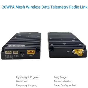
IP 메쉬 네트워크 라디오 모듈 커넥터

| 일련 번호 | 인터페이스 이름 | 인터페이스 정의 | 말 |
| 1 | 전원 인터페이스 | 전원 공급 장치 양성 | XT30PW-M, 외부 5V-28V 전원 공급 장치 또는 배터리. |
| 음의 전원 공급 장치 | |||
| 2 | 모드 제어 | 기음 | 구성 모드 |
| 디 | 데이터 투명 전송 모드 | ||
| 3 | 데이터 인터페이스 | 3.3V 전원 출력 | 로드 ≦ 150ma |
| 직렬 포트 TX (비) | TTL3.3V 레벨을 지원합니다, RS232 수준, RS485 레벨. 주문을하기 전에 미리 의사 소통하십시오. | ||
| 직렬 포트 Rx (에이) | |||
| 땅 | 데이터 장소 | ||
| 패션 0 | 작업 모드 구성 핀의 경우, 사양 시트를 참조하십시오. | ||
| ACK | 모듈 구성 상태 표시 신호. | ||
| 4 | 상태 표시기 | PWR 전력 표시등 | 전원이 입력되면 불이 켜집니다. |
| TX 전송 표시등 | 파워 온 자체 테스트가 잠깐 켜집니다, 데이터가 전송 될 때 표시등이 밝아집니다.. | ||
| RX 수신 표시등 | 파워 온 자체 테스트가 잠깐 켜집니다, 데이터를 수신 할 때 표시등이 밝아집니다.. | ||
| CA 간섭 표시등 | 전원 온도 자체 테스트 중에 간단히 밝아지고 구성 모드에서 켜집니다.. 투명 전송 모드에서:
불이 켜져 있을 때, 공기 인터페이스에 간섭이 있음을 의미합니다. 빛이 더 밝습니다, 간섭이 더 강해집니다. |
||
| FU 데이터 캐시 표시기 | 데이터 캐시가 가득 차면 켜집니다. | ||
| HFU 데이터 캐시 표시기 | 데이터 캐시가 반으로 가득 차면 켜집니다. | ||
| 5 | RF 출력 | RF 출력 인터페이스 | SMA-K, |
핵심 모듈 핀 및 정의

| 약어 | 설명하다 |
| 에서 | 디지털 입력 |
| ~하다 | 디지털 출력 |
| 부분 | 디지털 입력 또는 출력 |
| 피 | 힘 |
| 지 | 지면 |
핀 정의 테이블
| 핀 번호 | 핀 이름① | 유형 | 기술 |
| 1 | RF_TR0 | ~하다 | 표시 및 지표 신호를받습니다, 낮은 레벨이 전송 중입니다, 높은 수준이 받고 있습니다 (외부 제어 무선 주파수 스위치) |
| 2 | RF_TR1 | ~하다 | 표시 및 지표 신호를받습니다, 높은 수준이 전송되고 있습니다, 낮은 수준이 수신되고 있습니다 (외부 제어 무선 주파수 스위치 또는 LED 표시등 표시등은 에어 인터페이스에 데이터 전송이 있음을 나타냅니다.) |
| 3 | RF_TXON | ~하다 | 전원 증폭기 활성화 신호, 낮은 수준은 꺼져 있습니다, 높은 수준의 수단 (외부 제어 전력 증폭기) |
| 4 | RF_RHON | ~하다 | 낮은 잡음 증폭기 활성화 신호, 낮은 수준은 꺼져 있습니다, 높은 수준의 수단 (외부 제어 저조음 증폭기) |
| 5 | 캐리어 _s | ~하다 | Carrier_Sense 캐리어 프레임 청취 표시 신호, 높은 레벨은 에어 인터페이스에 캐리어가 있음을 의미합니다., 외부 LED 표시등이 연결되어 공기 인터페이스에 데이터 수신이 있음을 나타냅니다.. |
| 6 | ACK | ~하다 | 모듈 구성 상태 표시 신호, 높은 레벨은 구성이 완료되었음을 의미합니다, 낮은 레벨은 구성이 진행 중임을 의미합니다 |
| 7 | 입력③ | 에서 | 모듈이 활성화 신호를 켜십시오, 낮은 레벨 모듈이 꺼져 있습니다, 높은 레벨 또는 플로팅 모듈이 켜져 있습니다 |
| 8 | 패션 0 | 에서 | 모듈 작업 모드 선택 신호, 특정 기능 설명이 표에 나와 있습니다 6 |
| 9 | 모드 1 | 에서 | |
| 10 | GND | 지 | GND |
| 11 | UART_RXD | 에서 | 모듈 직렬 포트 수신 핀 |
| 12 | UART_TXD | ~하다 | 모듈 직렬 포트 송신기 핀 |
| 13 | Half_full | ~하다 | 모듈 데이터 캐시 표시 신호, 높은 레벨은 데이터 캐시가 절반으로 가득 차 있음을 의미합니다 |
| 14 | 가득한 | ~하다 | 모듈 데이터 캐시 표시 신호, 높은 레벨은 데이터 캐시가 가득 차 있음을 의미합니다 |
| 15 | GND | 지 | GND |
| 16 | JTAG_TCK | 에서 | 모듈 프로그래밍 핀② |
| 17 | JTAG_TDI | 에서 | |
| 18 | jtag _tdo | ~하다 | |
| 19 | jtag _tms | 에서 | |
| 20 | jtag _trst | 에서 | |
| 21 | GND | 지 | GND |
| 22 | GND | 지 | GND |
| 23 | VCC | 피 | 외부 3.6V ~ 5V 배터리 또는 전원 공급 장치 |
| 24 | VCC | 피 | 외부 3.6V ~ 5V 배터리 또는 전원 공급 장치 |
| 25 | 에 | AIO | RF 신호 입력/출력 핀, 외부 50Ω 안테나 또는 외부 RF 프론트 엔드에 연결, 선택적으로 IPEX에 연결되었습니다 1. |
| 26 | GND | 지 | GND |
노트:
- 모듈은 내부적으로 3.3V LDO로 규제됩니다, 그리고 모든 디지털 iOS가 있습니다 3.3 lvttl 레벨;
- 후속 소프트웨어 업그레이드를 용이하게하기 위해, 핀 헤더 또는 커넥터로 모듈 프로그래밍 핀을 이끌어내는 것이 좋습니다.;
- EN 핀은 전원 공급 장치에 직접 연결할 수 없습니다.. 전원 공급 장치에 연결 해야하는 경우, 현재 제한 저항을 추가하거나 3.3V LVTTL 레벨 제어 스위치를 사용해야합니다.;


야코프 –
이 IP 메시 무선 모듈은 군집 드론 운용을 위한 획기적인 제품입니다.! 자가 치유 네트워크는 전 세계에서 완벽한 통신을 유지했습니다. 50+ 산림 수색 임무 중 드론, 장애물로 인해 직접 링크가 차단된 경우에도. 거의 0에 가까운 대기 시간과 자동 노드 동기화로 시속 60마일의 속도를 유지했습니다., 군사급 암호화로 데이터 무결성을 보장하는 동시에. 설정은 플러그 앤 플레이 방식으로 이루어졌으며 복잡한 코딩이 필요하지 않았으며 적응형 주파수 호핑으로 도시의 RF 간섭을 쉽게 제거했습니다.. 견고한 군집 지능을 요구하는 재난 대응 팀 및 공중 조명 쇼용, 이 모듈은 거의 텔레파시처럼 느껴지는 방탄 연결성을 제공합니다.. 협업 드론의 미래가 여기에 있습니다!