


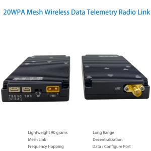
Μονάδα ραδιοφώνου δικτύου IP mesh για σμήνη drones
 χαρακτηριστικό
ο 1999 Η μονάδα ραδιοφώνου δικτύου IP mesh πραγματοποιεί επικοινωνία μεγάλων αποστάσεων χωρίς κέντρο μεταξύ κόμβων μεγάλης κλίμακας.
Όλοι οι κόμβοι μπορούν να επικοινωνούν ανεξάρτητα χωρίς να παρεμβαίνουν μεταξύ τους. Επιλύει τα προβλήματα της μεγάλης κλίμακας πυκνής πρόσβασης καναλιών, ασύρματη μετάδοση, δυναμική δικτύωση, και μη επανδρωμένα συμπλέγματα.
Απαιτούνται τεχνικά προβλήματα όπως η ευέλικτη αναδιοργάνωση και η συνεργασία σε πραγματικό χρόνο για να γίνει αντιληπτό ότι το δίκτυο σμήνους έχει την ικανότητα δικτύωσης μιας βιολογικής συμπεριφοράς που μοιάζει με σμήνος, αυτόνομη δικτύωση βάσει σεναρίων, ευέλικτη αναδιοργάνωση και έξυπνες δυνατότητες συνεργασίας.
ο 1999 Η μονάδα ραδιοφώνου δικτύου IP mesh έχει τα παρακάτω χαρακτηριστικά:
μεγάλης χωρητικότητας μεγάλης κλίμακας δυνατότητες πρόσβασης κόμβων;
16-δυνατότητες κάλυψης δικτύου αυτο-οργάνωσης hop;
εξαιρετικά χαμηλή καθυστέρηση;
απλό και εύκολο στη χρήση
ο 1999 Η μονάδα ραδιοφώνου δικτύου IP mesh μπορεί να χρησιμοποιηθεί για drones σμήνος, το διαδίκτυο των πραγμάτων, συνδέσμους δεδομένων, τηλεχειριστήριο, Σενάρια εφαρμογών όπως η συλλογή δεδομένων, τεχνητή νοημοσύνη, και ατομικό στρατιωτικό εξοπλισμό.
Προσδιορισμός
- Περιοχή συχνοτήτων: 825MHz~850MHz ή 902~928Mhz
- RF εύρους ζώνης: 1MHz/500kHz/250kHz/125kHz
- Ρυθμός δεδομένων διεπαφής αέρα: μέγιστο 740kbps@1MHz, 370kbps@500kHz, 185kbps@250kHz, 92kbps@125kHz
- Υποστηριζόμενος αριθμός κόμβων: το πολύ 1024
- Αριθμός αναπήδησης δικτύου: το πολύ 16 λυκίσκος.
- Πλήρης επικοινωνία πολλαπλών εργασιών: υποστήριξη;
- Ορατή απόσταση: ≥30 χιλιόμετρα;
- Χωρίς κέντρο ad hoc (πλέγμα) δίκτυο: Υποστηρίζει ad hoc δίκτυο χωρίς κέντρο, και η ζημιά οποιουδήποτε κόμβου στο δίκτυο δεν θα επηρεάσει την επικοινωνία;
- Αναπήδηση συχνότητας: δεν υποστηρίζει αναπήδηση συχνότητας και αναπήδηση συχνότητας, τη μέγιστη συχνότητα ταχύτητα αναπήδησης είναι 1800 φορές το δευτερόλεπτο
- Δίκτυο αυτοοργάνωσης χωρίς κέντρο: Υποστηρίζει χωρίς κέντρο αυτο-οργάνωσης δίκτυο. Η ζημιά οποιουδήποτε κόμβου στο δίκτυο δεν θα επηρεάσει την επικοινωνία.
- Χρόνος εγκατάστασης δικτύου: στα πλαίσια 1 δεύτερος
- Καθυστέρηση μετάδοσης από άκρο σε άκρο: τουλάχιστον 2 ms
- Δυναμική τοπολογία: Υποστηρίζει δυναμική τοπολογία, υποστηρίζει κόμβους που ενώνονται και φεύγουν, και μπορεί να επικοινωνεί κανονικά ακόμα κι αν αλλάξει ή παραμορφωθεί η τοπολογία του δικτύου.
- Χρόνος αυτοσυντηρούμενος: το δίκτυο μπορεί να κατασκευαστεί χωρίς εξωτερικό χρονισμό
- Ισχύς μετάδοσης: 0.5W (μπορεί να συνδεθεί σε εξωτερικό ενισχυτή υψηλής ισχύος)
- Λήψη ευαισθησίας: -114dBm@125kHz, -111dBm@250kHz, -108dBm@500kHz, -105dBm@1MHz
- Χαμηλή κατανάλωση ρεύματος: Η κατανάλωση ενέργειας είναι μικρότερη από 1 watt κατά τη λήψη και λιγότερο από 5 watt κατά τη μετάδοση.
- Σταθερότητα συχνότητας: ≤1ppm
- Κρυπτογράφηση: Κρυπτογράφηση AES128-bit
- Τάση λειτουργίας: 3.6~5V
- Θερμοκρασία λειτουργίας: -30+75℃
- Ενότητα βάρους: <45σολ
Παράμετροι εργασίας
| παράμετρος | κατάσταση | μικρότερο | τυπικός | το πολύ | μονάδα |
| συχνότητα εργασίας | 825 | 850 | MHz | ||
| Θερμοκρασία λειτουργίας | -30 | 25 | +75 | ℃ | |
| Τάση λειτουργίας | 3.6 | 4.2 | 5 | ΣΕ | |
| ισχύος εκπομπής | @VCC=5V | 26 | 27 | 28 | dBm |
| Λήψη της ευαισθησίας | 125kHz | -116 | -114 | -112 | dBm |
| 250kHz | -113 | -111 | -109 | ||
| 500kHz | -110 | -108 | -106 | ||
| 1MHz | -107 | -105 | -103 | ||
| Μέγιστη ισχύς εισόδου RF | +10 | dBm | |||
| Ρεύμα ύπνου | @EN=0 | 40 | uA | ||
| λαμβάνουν ρεύμα | 200 | 240 | mA | ||
| Ρεύμα εκπομπής | @VCC=5V,0.5W | 1000 | 1200 | mA |
※Σημείωμα:Εάν οι συνθήκες εργασίας της μονάδας υπερβαίνουν τις παραπάνω οριακές τιμές, μπορεί να προκαλέσει μόνιμη βλάβη στη μονάδα.
Υποδοχή μονάδας ραδιοφώνου δικτύου IP mesh

| αύξων αριθμός | Όνομα διεπαφής | Ορισμός διασύνδεσης | Παρατήρηση |
| 1 | Διασύνδεση ισχύος | Τροφοδοτικό θετικό | XT30PW-M, εξωτερικό τροφοδοτικό 5V-28V ή μπαταρία. |
| Αρνητικό τροφοδοτικό | |||
| 2 | Έλεγχος λειτουργίας | ντο | λειτουργία διαμόρφωσης |
| ρε | Λειτουργία διαφανούς μετάδοσης δεδομένων | ||
| 3 | διασύνδεσης δεδομένων | 3.3Έξοδος ισχύος V | Φορτίο ≦150mA |
| Σειριακή θύρα Tx (σι) | Υποστήριξη επιπέδου TTL3.3V, Επίπεδο RS232, Επίπεδο RS485. Επικοινωνήστε εκ των προτέρων πριν κάνετε μια παραγγελία. | ||
| Σειριακή θύρα Rx (ΕΝΑ) | |||
| γη | τόπος δεδομένων | ||
| Λειτουργία 0 | Για καρφίτσες διαμόρφωσης λειτουργίας λειτουργίας, ανατρέξτε στο φύλλο προδιαγραφών. | ||
| ACK | Σήμα ένδειξης κατάστασης διαμόρφωσης μονάδας. | ||
| 4 | Ένδειξη κατάστασης | Ενδεικτική λυχνία ισχύος PWR | Ανάβει όταν γίνεται είσοδος ρεύματος. |
| Ενδεικτική λυχνία εκπομπής TX | Ο αυτόματος έλεγχος ενεργοποίησης ανάβει για λίγο, και η ενδεικτική λυχνία ανάβει κατά τη μετάδοση δεδομένων. | ||
| Ενδεικτική λυχνία λήψης RX | Ο αυτόματος έλεγχος ενεργοποίησης ανάβει για λίγο, και η ενδεικτική λυχνία ανάβει όταν λαμβάνονται δεδομένα. | ||
| Ενδεικτική λυχνία παρεμβολής CA | Ανάβει για λίγο κατά τη διάρκεια του αυτοδιαγνωστικού ελέγχου ενεργοποίησης και παραμένει ενεργοποιημένο στη λειτουργία διαμόρφωσης. Σε διαφανή λειτουργία μετάδοσης:
Όταν το φως είναι αναμμένο, σημαίνει ότι υπάρχει παρεμβολή στη διεπαφή αέρα. Όσο πιο φωτεινό είναι το φως, τόσο ισχυρότερη είναι η παρεμβολή. |
||
| Ένδειξη κρυφής μνήμης δεδομένων FU | Ανάβει όταν η κρυφή μνήμη δεδομένων είναι πλήρης. | ||
| Ένδειξη κρυφής μνήμης δεδομένων HFU | Ανάβει όταν η κρυφή μνήμη δεδομένων είναι μισογεμάτη. | ||
| 5 | Έξοδος RF | διεπαφή εξόδου RF | SMA-K, |
Καρφίτσες και ορισμοί της μονάδας πυρήνα

| συντομογραφία | περιγράφω |
| ΑΠΟ | Ψηφιακή είσοδος |
| ΚΑΝΩ | Ψηφιακή έξοδος |
| ΜΕΡΟΣ | Ψηφιακή είσοδος ή έξοδος |
| Π | Εξουσία |
| σολ | Εδαφος |
πίνακας ορισμού καρφίτσας
| Pin NO | Όνομα καρφίτσας① | Τύπος | Περιγραφή |
| 1 | RF_TR0 | ΚΑΝΩ | Αποστολή και λήψη ενδεικτικών σημάτων, χαμηλό επίπεδο εκπέμπει, υψηλό επίπεδο λαμβάνει (εξωτερικός διακόπτης ραδιοσυχνοτήτων ελέγχου) |
| 2 | RF_TR1 | ΚΑΝΩ | Αποστολή και λήψη ενδεικτικών σημάτων, υψηλό επίπεδο μεταδίδει, χαμηλό επίπεδο λαμβάνει (Ο διακόπτης ραδιοσυχνότητας εξωτερικού ελέγχου ή η ενδεικτική λυχνία LED υποδεικνύει ότι υπάρχει μετάδοση δεδομένων στη διεπαφή αέρα) |
| 3 | RF_BOX | ΚΑΝΩ | Σήμα ενεργοποίησης ενισχυτή ισχύος, χαμηλό επίπεδο σημαίνει απενεργοποιημένο, υψηλό επίπεδο σημαίνει επάνω (ενισχυτής ισχύος εξωτερικού ελέγχου) |
| 4 | RF_RXON | ΚΑΝΩ | Σήμα ενεργοποίησης ενισχυτή χαμηλού θορύβου, χαμηλό επίπεδο σημαίνει απενεργοποιημένο, υψηλό επίπεδο σημαίνει επάνω (Εξωτερικά ελεγχόμενος ενισχυτής χαμηλού θορύβου) |
| 5 | CARRIER_S | ΚΑΝΩ | Σήμα ένδειξης ακρόασης καρέ CARRIER_SENSE φορέα, υψηλό επίπεδο σημαίνει ότι υπάρχει ένας φορέας στη διεπαφή αέρα, και μια εξωτερική ενδεικτική λυχνία LED μπορεί να συνδεθεί για να υποδείξει ότι υπάρχει λήψη δεδομένων στη διεπαφή αέρα. |
| 6 | ACK | ΚΑΝΩ | Σήμα ένδειξης κατάστασης διαμόρφωσης μονάδας, υψηλό επίπεδο σημαίνει ότι η διαμόρφωση έχει ολοκληρωθεί, χαμηλό επίπεδο σημαίνει ότι η διαμόρφωση είναι σε εξέλιξη |
| 7 | ΣΕ③ | ΑΠΟ | Σήμα ενεργοποίησης ενεργοποίησης μονάδας, Η μονάδα χαμηλού επιπέδου είναι απενεργοποιημένη, Η μονάδα υψηλού επιπέδου ή πλωτής είναι ενεργοποιημένη |
| 8 | MODE0 | ΑΠΟ | Σήμα επιλογής τρόπου λειτουργίας μονάδας, Η περιγραφή της συγκεκριμένης λειτουργίας φαίνεται στον Πίνακα 6 |
| 9 | MODE1 | ΑΠΟ | |
| 10 | GND | σολ | GND |
| 11 | UART_RXD | ΑΠΟ | Πείρο λήψης σειριακής θύρας μονάδας |
| 12 | UART_TXD | ΚΑΝΩ | Πείρο πομπού σειριακής θύρας μονάδας |
| 13 | ΜΙΣΟΓΕΜΑΤΟ | ΚΑΝΩ | Ενδεικτικό σήμα κρυφής μνήμης δεδομένων μονάδας, υψηλό επίπεδο σημαίνει ότι η κρυφή μνήμη δεδομένων είναι μισογεμάτη |
| 14 | ΓΕΜΑΤΟΣ | ΚΑΝΩ | Ενδεικτικό σήμα κρυφής μνήμης δεδομένων μονάδας, υψηλό επίπεδο σημαίνει ότι η κρυφή μνήμη δεδομένων είναι πλήρης |
| 15 | GND | σολ | GND |
| 16 | JTAG_TCK | ΑΠΟ | Καρφίτσα προγραμματισμού μονάδας② |
| 17 | JTAG_TDI | ΑΠΟ | |
| 18 | JTAG_TDO | ΚΑΝΩ | |
| 19 | JTAG _TMS | ΑΠΟ | |
| 20 | JTAG _TRST | ΑΠΟ | |
| 21 | GND | σολ | GND |
| 22 | GND | σολ | GND |
| 23 | VCC | Π | Εξωτερική μπαταρία 3,6V~5V ή τροφοδοτικό |
| 24 | VCC | Π | Εξωτερική μπαταρία 3,6V~5V ή τροφοδοτικό |
| 25 | ΕΠΙ | AIO | Πείρο εισόδου/εξόδου σήματος RF, συνδεδεμένο σε εξωτερική κεραία 50Ω ή εξωτερική πρόσοψη RF, προαιρετικά συνδεδεμένο με IPEX 1. |
| 26 | GND | σολ | GND |
Σημείωση:
- Η μονάδα ρυθμίζεται εσωτερικά από 3,3V LDO, και όλα τα ψηφιακά IO βρίσκονται σε 3.3 Επίπεδο LVTTL;
- Προκειμένου να διευκολυνθούν οι επόμενες αναβαθμίσεις λογισμικού, Συνιστάται να βγάλετε έξω τις ακίδες προγραμματισμού της μονάδας με κεφαλίδες ακίδων ή συνδέσμους;
- Ο ακροδέκτης EN δεν μπορεί να συνδεθεί απευθείας στο τροφοδοτικό. Εάν χρειάζεται να συνδεθεί στο τροφοδοτικό, πρέπει να προστεθεί μια αντίσταση περιορισμού ρεύματος ή να χρησιμοποιηθεί ένας διακόπτης ελέγχου στάθμης 3,3 V LVTTL;


Γιακόφ –
Αυτή η μονάδα ραδιοφώνου IP mesh είναι μια σημαντική ανακάλυψη για τις λειτουργίες σμήνος drone! Το αυτοθεραπευόμενο δίκτυο του διατήρησε άψογη επικοινωνία 50+ drones κατά τη διάρκεια της αποστολής μας για αναζήτηση δασών, ακόμη και όταν τα εμπόδια μπλοκάρουν τους άμεσους συνδέσμους. Η σχεδόν μηδενική καθυστέρηση και ο αυτόματος συγχρονισμός κόμβων διατήρησαν τους σχηματισμούς σφιχτούς στα 60 mph, ενώ η κρυπτογράφηση στρατιωτικού βαθμού εξασφάλιζε την ακεραιότητα των δεδομένων. Η εγκατάσταση ήταν plug-and-play—δεν χρειαζόταν πολύπλοκη κωδικοποίηση—και η προσαρμοστική αναπήδηση συχνότητας απομάκρυνε αβίαστα τις αστικές παρεμβολές RF. Για ομάδες αντιμετώπισης καταστροφών και εκπομπές εναέριου φωτός απαιτητική ευφυΐα σμήνους από πέτρες, Αυτή η μονάδα παρέχει αλεξίσφαιρη συνδεσιμότητα που μοιάζει σχεδόν τηλεπαθητική. Το μέλλον των συνεργατικών drones είναι εδώ!