


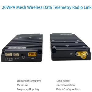

0.5W or 20WPA Mesh Wireless Data Telemetry Radio Link transceiver

Stay connected anywhere – Our drone mesh data radio link ensures seamless real-time communication.
Reliable data transfer – Experience uninterrupted connectivity with our advanced radio link.
Fly farther, communicate better – Optimized for long-range drone data transmission.
Table of Contents
Advantage
- Wireless link rates of up to 740 kbps are supported.
- It supports point-to-point, point-to-multi-point, multi-point-to-point, and mesh network topologies.
- It supports a mesh network with up to 1024 nodes.
- High sensitivity level of -114dBm at 125kHz.
- It supports the frequency-hopping spread spectrum (FHSS).
- Support 2X Serial Port.
Our self-organizing mesh network data link radio enables centerless, long-distance communication between large-scale nodes. Each node can independently communicate with others without interference, supporting dense node access for wireless transmission, dynamic networking, and flexible reorganization. It features full-multiplexing communication, allowing nodes to transmit and receive data simultaneously without disruption. Even without a central hub, any node can seamlessly inter-operate with all other nodes in the network, ensuring efficient and interference-free interconnectivity.
Our data link mesh radio supports large-scale node access and multi-hop self-organizing networks, featuring 20W transmit power, -114dBm sensitivity, a maximum effective data transmission rate of 740kbps, and ultra-low latency of 2ms. It is ideal for applications such as swarming drones, the Internet of Things, data chains, remote control, data collection, artificial intelligence, military equipment, and more.
Our data link mesh radio is available in multiple models, all featuring the same appearance and functionality, differing only in operating frequency bands and networking scale.
20W data link mesh radio models
| Model | Network size | Frequency band | Optional uart |
| Vcan2086-F800 | Max. 256 nodes, up to 3 hops | 820~854MHz | TTL or RS232 or RS422 |
| Vcan2086-F900 | Max. 256 nodes, up to 3 hops | 902~928MHz | TTL or RS232 or RS422 |
| Vcan2086-H800 | Max. 1024 nodes, up to 16 hops | 820~854MHz | TTL or RS232 or RS422 |
| Vcan2086-H900 | Max. 1024 nodes, up to 16 hops | 902~928MHz | TTL or RS232 or RS422 |
Feature
-
Frequency: Different models support various frequency bands 820-854Mhz or 902-928Mhz. (refer to the model table).
-
Bandwidth: Selectable options of 1MHz, 500kHz, 250kHz, and 125kHz.
-
Number of Nodes & Hops: Supports up to 1024 nodes with a maximum of 16 hops or 256 nodes with up to 3 hops (see model table).
-
Frequency Hopping Speed:
-
1MHz: Over 1800 hops per second
-
500kHz: Over 900 hops per second
-
250kHz: Over 450 hops per second
-
125kHz: Over 225 hops per second
-
-
Effective Data Rate:
-
1MHz: Up to 740kbps
-
500kHz: Up to 370kbps
-
250kHz: Up to 185kbps
-
125kHz: Up to 92kbps
-
-
Full-Multiplexing Communication: Supported.
-
Air-to-Ground Line-of-Sight Distance: ≥300km.
-
Centerless Self-Organized Network: Supports centerless networking, ensuring uninterrupted communication even if a node is destroyed.
-
Network Construction Time: Within 1 second.
-
Wireless Transmission Delay: As low as 2ms.
-
Dynamic Topology: Supports dynamic topology, allowing nodes to join and leave without disrupting communication.
-
RF Power: 20W (43dBm).
-
Sensitivity:
-
125kHz: -114dBm
-
250kHz: -111dBm
-
500kHz: -108dBm
-
1MHz: -105dBm
-
-
Frequency Stability: ≤1ppm.
-
Modulation & Coding: QPSK modulation with LDPC coding.
-
Encryption: 128-bit encryption for secure communication.
-
Low Power Consumption:
-
Receiving mode: <1.5W (0.06A @ 24V).
-
Transmission power consumption (varies by data rate):
-
1.2KB/s → ~2.4W (0.1A @ 24V)
-
3.4KB/s → ~3.9W (0.16A @ 24V)
-
6.4KB/s → ~5.5W (0.23A @ 24V)
-
12KB/s → ~9.6W (0.4A @ 24V)
-
26KB/s → ~19.2W (0.8A @ 24V)
-
37KB/s → ~24W (1A @ 24V)
-
48KB/s → ~32W (1.35A @ 24V)
-
-
-
Operating Voltage: Default 24V, with a wide input range of 7-36V. Transmission power varies with voltage:
-
7V: 2W
-
12V: 5W
-
18V: 10W
-
24V: Slightly above 20W
-
20-36V: 20W-30W
-
Power supply requirement: ≥2.5A @ 24V (20W).
-
-
Operating Temperature: -40°C to +55°C.
-
Dimensions: (0.5 watts PA ) 50 x 50 x 16 mm; (20 watts PA) 82.5 × 52 × 16mm.
-
Weight: (0.5 watts PA ) 60 grams; (20 watts PA )88 grams.


Specification
| I/O | Description |
| J30JZ-9PIN connector | Power-input, uart, M0 control signals |
| M1 Dip Switch | M1 control signal |
| SMA female | Antenna port, the required antenna impedance is 50Ω |
J30JZ-9PIN connector
J30JZ-9PIN connector PIN signal (when assembled as TTL3.3Vor RS232 uart port)
| No. | PIN | Description | Input or Output |
| 1 | M0 | M0 control signal | I |
| 2 | TX | Uart transmission pin | O |
| 3 | RX | Uart receiving pin | I |
| 4 | GND | GND of uart port | O |
| 5 | NULL | Null | IO |
| 6 | VDD | Power input VDD | I |
| 7 | VDD | Power input VDD | I |
| 8 | GND | Power input GND | I |
| 9 | GND | Power input GND | I |
J30JZ-9PIN connector PIN signal (when assembled as RS422 uart port)
| No. | PIN | Description | Input or Output |
| 1 | M0 | M0 control signal | I |
| 2 | 422_TX+ | RS422 port transmission positive pin | O |
| 3 | 422_TX- | RS422 port transmission negative pin | O |
| 4 | 422_RX+ | RS422 port receiving positive pin | I |
| 5 | 422_RX- | RS422 port receiving negative pin | I |
| 6 | VDD | Power input VDD | I |
| 7 | VDD | Power input VDD | I |
| 8 | GND | Power input GND | I |
| 9 | GND | Power input GND | I |
Power input
The supply voltage range of OUR is 7V~36V, 24V as default.
Uart port
Before shipment, the UART port can be configured as a TTL, RS232, or RS422 UART port based on customer requirements. The TTL/RS232 UART port operates with an 8-bit data format, 1 stop bit, and no parity check.
-
Configuration Mode: Fixed baud rate of 9600.
-
Data Transparent Mode: Configurable baud rates: 9600, 19200, 38400, 57600, 115200, 230400, 460800, or 921600.
Recommended Baud Rates for Different RF Bandwidths:
-
1MHz RF Bandwidth: 921600 baud
-
500kHz RF Bandwidth: 460800 baud
-
250kHz RF Bandwidth: 230400 baud
-
125kHz RF Bandwidth: 115200 baud
Matching the UART baud rate with the wireless throughput ensures stable data transmission and prevents packet loss. The UART ports are primarily used for radio parameter configuration and data transmission.
M1 Dip Switch
The M1 and M0 signals (with M0 located on the J30JZ-9PIN connector) control the operating mode of the radio.
Operating Modes
The radio supports two modes:
-
Data Transparent Transmission Mode
-
Configuration Mode
Users can set the system mode by adjusting the voltage levels of M0 and M1:
-
Configuration Mode: Activated when M0 and M1 have different voltage levels.
-
Transparent Transmission Mode: Activated when M0 and M1 have the same voltage level.
By default, the M0 and M1 pins are internally pulled up to a high level, placing the system in transparent mode. To switch to configuration mode, suspend M0 and turn the M1 dip switch to the “C” Configuration side. To return to transparent transmission mode, turn the M1 dip switch to the “D” Data side. Mode switching occurs in real time without requiring a system restart.
Configuration Mode
-
The radio only responds to configuration commands and does not transmit received serial data to the wireless port.
-
Incoming signals from the wireless port are not forwarded to the serial port.
-
The UART baud rate is fixed at 9600, with 8 data bits, 1 stop bit, and no parity check bit.
-
Only local configuration parameters can be modified.
Transparent Transmission Mode
-
If the received serial data is a configuration packet, the radio performs parameter configuration.
-
If the received serial data is not a configuration packet, it is transmitted to the wireless port, and incoming signals from the wireless port are forwarded to the serial port.
-
Both local and remote parameter configurations are supported.
Indicator LEDs
| LED | Description |
| PWR | Power led, Red light on normal powered. |
| TX | Green, data transmission led, briefly light during power on self-test, light when data is transmitting. |
| RX | Green, data receiving led, briefly light during power on self-test, light when receiving data. |
| CA | Blue, interference led, briefly light during power on self-test, light in configuration mode. In transparent transmission mode: When it light on, it means exist interference and the brighter the light, the stronger the interference signal. |
| FU | Blue, data cache indicator led, briefly light during power on self-test, light when data cache is full. |
| HFU | Blue, data cache indicator led, briefly light during power on self-test, light when data cache is half full. |
To maintain high communication quality, the system includes an internal data buffer with an adjustable size. A larger buffer reduces the risk of data loss but may increase latency. The buffer status can be monitored using the FU and HFU indicator LEDs.
It is generally recommended that when the HFU LED is lit, the host computer should temporarily pause data transmission to prevent the buffer from reaching capacity and causing data loss.
Software Download
Parameter Configuration Software: Data Link Management Software
https://drive.google.com/file/d/1xX4wJY5-kwPiVSg7EQjIn4ryIHty_Fzx/view?usp=drive_link
How to Switch Languages from Chinese to English?
Serial Port Debugging Tool: ComTransmit.exe
https://drive.google.com/file/d/1xdue01ntCGDdfmTMMX3Oc9tsRXevrYIN/view?usp=drive_link
How to Switch Languages from Chinese to English?
Users Manual
Please click to download the Users Manual PDF


Fast deployment – Get up and running in minutes with our plug-and-play solution.
Future-ready technology – Stay ahead with cutting-edge drone communication.
Connect, control, conquer – Take your drone operations to the next level.


Reviews
There are no reviews yet.