


-
High-Performance Cavity Bandpass Filter for RF Systems – Custom Frequency and Bandwidth Options
-
RF Cavity Filter with Low Insertion Loss and Excellent Out-of-Band Rejection
-
Professional RF Bandpass Filter – Precision Tuning and High Power Handling up to 100W
Customizable Frequency Interface Cavity Bandpass Filter for RF Systems
Table of Contents
Overview
The Cavity Bandpass Filter with a customizable frequency interface is a high-performance RF filter designed for professional wireless communication, telemetry, and signal processing systems that demand superior selectivity and stability.
Engineered with precision-machined cavity resonators, this filter provides excellent frequency control, low insertion loss, and high out-of-band rejection, making it ideal for applications in mission-critical RF links, including drone video transmission, wireless surveillance, public safety communications, and base station signal conditioning.
With a center frequency of 320 MHz and bandwidth between 8–10 MHz, this bandpass filter ensures clean signal transmission within the passband while effectively suppressing unwanted frequencies outside the desired range.
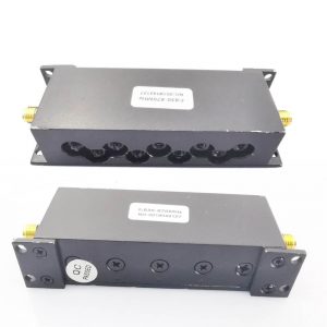
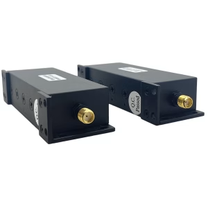
Its rugged cavity structure and SMA-50K RF connectors guarantee mechanical stability and reliable electrical performance even under varying environmental conditions. The design also supports customizable center frequencies and bandwidths to meet specific system integration requirements.
This model exemplifies the advantages of cavity filter technology—high power handling, excellent temperature stability, and low loss performance—making it a trusted choice for professional RF engineers and system integrators who require dependable filtering performance in compact, durable form factors.
Key Features
-
Customizable Frequency Interface
-
Supports customization of center frequency and bandwidth based on customer requirements.
-
Flexible interface options allow seamless integration with various RF front-end systems.
-
-
Excellent Bandpass Performance
-
Center Frequency: 320 MHz (customizable).
-
Bandwidth: 8–10 MHz.
-
Optimized cavity design provides sharp roll-off characteristics for precise frequency control.
-
-
Low Insertion Loss & Ripple
-
Insertion Loss ≤ 1.0 dB ensures minimal signal attenuation.
-
In-Band Ripple ≤ 0.5 dB maintains signal flatness and consistency within the passband.
-
-
Superior Out-of-Band Rejection
-
≥ 40 dB attenuation at ± 40 MHz from center frequency effectively eliminates adjacent channel interference.
-
Ensures clean spectral response and improved system signal-to-noise ratio.
-
-
High Power Handling Capability
-
Rated for up to 100 W RF power, suitable for medium- to high-power transmission systems.
-
Stable under continuous operation, with robust cavity design preventing thermal drift.
-
-
Excellent VSWR Performance
-
VSWR ≤ 1.2 ensures efficient power transfer and minimal signal reflection.
-
Ideal for impedance-matched RF circuits.
-
-
Rugged Construction and Durability
-
Aluminum alloy housing provides high mechanical strength and excellent shielding effectiveness.
-
Withstands vibration, impact, and harsh environmental conditions.
-
-
Stable Operation Over Wide Temperature Range
-
Operating Temperature: -35 °C to +65 °C.
-
Maintains consistent electrical performance across varying temperature conditions.
-
-
Compact and Easy to Integrate
-
Dimensions: 199 × 120 × 35 mm.
-
SMA-50K connectors provide secure and reliable RF connections.
-
Compact design suitable for rack-mounted, vehicle-mounted, or airborne equipment.
-
-
Tailored for Professional Applications
-
Designed to meet demanding requirements in COFDM video transmission, wireless command systems, and military-grade communication devices.
-
Technical Specifications
| Parameter | Specification |
|---|---|
| Center Frequency (Fo) | 320 MHz (Customizable) |
| Bandwidth | 8 – 10 MHz |
| Insertion Loss | ≤ 1.0 dB |
| In-Band Ripple | ≤ 0.5 dB |
| VSWR | ≤ 1.2 |
| Out-of-Band Rejection | ≥ 40 dB @ Fo ± 40 MHz |
| Power Handling | 100 W |
| Temperature Range | -35 °C ~ +65 °C |
| Connector Type | SMA-50K |
| Housing Material | Aluminum Alloy |
| Dimensions (L×W×H) | 199 × 120 × 35 mm |
| Weight | Approx. Customized per model |
Applications
This cavity bandpass filter is widely used in:
-
COFDM Wireless Video Transmission Systems – Ensures stable image transmission and reduces co-channel interference.
-
Drone and UAV Communication Links – Provides reliable frequency isolation for telemetry and video downlink.
-
Base Station RF Systems – Filters and conditions transmit/receive channels to maintain high-quality signals.
-
Wireless Repeater and Relay Systems – Prevents interference and ensures channel separation between multiple transceivers.
-
Public Safety and Military Communication Equipment – Maintains secure and interference-free signal paths in tactical environments.
-
RF Test and Measurement – Used as a precision filtering element in laboratory or production line setups.
Available Options
We offer customization services for various specifications to suit your project needs:
-
Frequency Range:
-
Adjustable from 100 MHz to 6 GHz depending on application.
-
-
Bandwidth:
-
Customizable from narrowband (1 MHz) to wideband (100 MHz or more).
-
-
Connector Type:
-
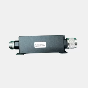
SMA, N-type, BNC, or other RF interface options available. (Male or Female connector)
-
-
Power Rating:
-
Configurable for standard (10–50 W) or high-power (up to 200 W) operation.
-
-
Mechanical Form Factor:
-
Available in standard cavity housing, rack-mounted, or PCB-integrated versions.
-
-
Filter Type:
-
Bandpass, Bandstop, Lowpass, or Highpass versions available upon request.
-
-
Environmental Options:
-
Hermetically sealed and vibration-resistant versions for airborne or outdoor use.
-
Ordering Information & Notes
When placing an order, please provide the following details to ensure proper configuration and fast delivery:
-
Center Frequency (Fo): Specify the desired working frequency (e.g., 320 MHz).
-
Bandwidth (BW): Indicate the required passband width (e.g., 8–10 MHz).
-
Connector Type: Choose SMA, N, or other preferred interfaces.
-
Power Handling: Specify expected input power level to match the correct design.
-
Mechanical Dimensions (if custom): Confirm size or mounting requirements.
-
Environmental Conditions: Specify if used outdoors, at high altitude, or under vibration.
-
Quantity & Lead Time: Mention project timeline to ensure production scheduling.
Tip: For optimal system performance, match the filter’s impedance (typically 50 Ω) with your transmitter and receiver front ends. Avoid overloading beyond the rated 100 W power limit.
Why Choose Our Cavity Bandpass Filter
-
-
Precision Engineering: Each filter is fine-tuned with advanced CNC-machined cavity resonators for superior frequency accuracy.
-
Low Loss, High Stability: Optimized design minimizes insertion loss while maintaining phase linearity.
-
Custom Solutions: Tailor-made filters available for unique system architectures and frequency plans.
-
Reliable Quality Control: Every unit undergoes rigorous RF testing for frequency response, VSWR, and rejection performance before shipment.
-
-
Experienced Manufacturing: Developed by a team with over a decade of expertise in COFDM wireless transmission and RF filter design.
Conclusion
The Customizable Frequency Interface Cavity Bandpass Filter offers a perfect balance between precision, durability, and adaptability. With its robust construction, low loss, and excellent out-of-band rejection, it stands out as an essential component for any RF communication or telemetry system requiring clean, stable, and interference-free signal transmission.
Whether you are building a drone link, video downlink, base station, or RF testing setup, this cavity filter delivers the performance and reliability professionals depend on.


FAQ
1. Can you make these filters? 300–500 MHz at 20 W and 100 W; 700–1000 MHz at 20 W and 100 W; 1300–1500 MHz at 20 W
Yes, we can design and manufacture RF bandpass filters for you. To provide a correct and precise quotation, please first confirm the following two parameters:
1. What is the out-of-band rejection frequency?
Please specify the frequency range(s) where out-of-band suppression is required, such as:
-
Frequencies below the passband
-
Frequencies above the passband
-
Any specific interference frequencies that must be rejected
2. How much out-of-band rejection is needed?
Please indicate the required rejection level in dB (e.g., 40 dB, 60 dB, or higher) at the specified out-of-band frequencies.
-
Customizable Frequency Cavity Filter for Drone, COFDM, and Wireless Video Systems
-
Low VSWR, High Selectivity RF Cavity Bandpass Filter for Clean Signal Transmission
-
Durable Bandpass Filter with SMA Connectors for Reliable RF Performance


iVcan.com –
I’ve been using the Customizable Frequency Interface Cavity Bandpass Filter for several months in our drone video transmission system, and the performance has been outstanding. The signal remains clean and stable even in complex RF environments, and the out-of-band rejection is excellent. The build quality is solid, and the SMA connectors ensure a reliable connection. What impressed me most is the low insertion loss and consistent frequency stability across temperature changes. This filter truly delivers professional-grade performance and reliability for critical RF applications.