


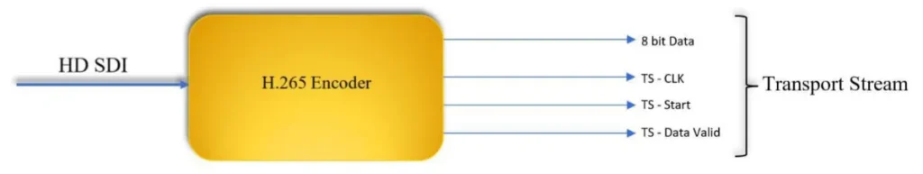
我们需要设备, 接收有关 SDI 全高清摄像机视频的信息 (串行数据接口) 上线并以 H.265 标准编码信息. 压缩数据必须以 DVB-T 传输 (地面数字视频广播) 或DVB-S标准. 设计模块的模拟输出可以接受I和Q信号, 以及调制信号.
目录
Q: 您的 SDI 视频编码器是否支持 TSI 输入 / 产量?
一个: 我们现有的编码板到调制板通过网口传输数据. 而不是你提到的TSI接口. 这并不影响发射器到接收器的使用. 这是发射器的内部接口.
Q: 你们的编码器解码板支持吗 525 i50 至 1080 P60关于视频格式?
一个: 现在我们的SDI视频编码器板支持高清: [email protected]/24Hz/25Hz/29.97Hz/30Hz/50Hz59.94Hz/60Hz 和 [email protected]/24Hz/25Hz/29.97Hz/30Hz/50Hz/59.94Hz/60Hz. 它不支持 525 i50视频格式, 可以吗?
Q: 你们的SDI COFDM DVB-T H265 SDI编码器射频输出功率支持0~10dBm吗?

一个: 你需要的输出频率点从400Mhz到2800Mhz很宽.
这么宽的频点下很难实现0~10dBm的输出, 并且板上加功率放大器会增加功耗和发热量 (你还提到不需要风扇散热).
您是否愿意同意我们现有的 -3 到 -10dBm 输出,然后添加您自己的 PA (功率放大器)?
Q: 您的 COFDM DVB-T H265 SDI 编码器的尺寸是多少?

您有特殊尺寸要求吗? 我们现有的尺寸是70x45mm.
一个: 我们现有的视频编码器和解码器板可以满足您的项目需求.
我的工程师最担心的是你们公司, 作为广电行业的一员,对图像视频质量有着比较高的要求.
我们的视频编码板将执行有损压缩以实现低延迟. 能否拿一组现有的样品来测试并确认图像质量? 如果您认为我们的样品可以满足贵公司的要求, 我们将根据贵公司的要求重新设计和绘制板卡.

Q: 您能提供有关VBR的更多信息吗?
通过将视频应用于TX, VBR参数会随着时间而变化,而不是静态值. 您能提供有关此的更多信息吗?
一个: VBR是发射器的视频编码比特率. 由于视频图片动态变化, VBR当然是可变的, 但是它围绕传输系统设置的编码比特率波动: 7.81*0.8= 6.248Mbps.
Q: 尽管我的接收器上有闪存存储, REC OFF,屏幕上没有显示存储. 为什么这会发生?
您在描述中说: KEY2: 视频录制的切换按钮, 短按改变状态. 接收器会自动检查存储设备 (微型 SD 卡或 USB 磁盘, 优先SD卡) 开机后插入存储设备开始录像. 只需按按钮停止或再次记录.
一个: 接收系统无法检测到USB闪存驱动器. USB闪存驱动器需要格式化为我们系统可以识别的格式.
Q: B1和B2均为零. 这表明有一个 0 % 咬合错误率!!! 这些参数的哪个范围是可以接受的?
一个: 一点错误率的发生可能会导致视频图像问题. 当位错误率很小时, 它不会影响视频图像效果.

Q: 我可以自定义程序员屏幕内容吗?
一个: 配置面板的显示内容 (程序员) 不向客户开放进行修改.
Q: 为什么没有编程S2频道? 看来第二个调谐器目前不起作用.
一个: S2是指接收天线 2, 可以正常工作. 频率和带宽为相同的S1和S2.
Q: 为什么我计算的延迟很大? 在附近 470 女士.
在您的描述中: 我们的接收器模块的默认正常功能可以与H.265发射器模块配对. 从发射端输入到接收端HDMI屏幕显示的高清视频延迟约为200ms至250ms.
一个: 我们测试的延迟约为250ms. 你是怎么测试的? 我们测试的延迟方式, 请检查 YouTube视频链接.
Q: 您的SDI编码器发射器和解码器接收器模块的延迟有多少?
我记得您说过您优化了协议以提高延迟. 因为我不使用您的快速H.264延迟 (130 女士) 我们的设置应该有多少延迟?
一个: 您确认您需要支持H265, 但不是H264低延迟模式. 达到低延迟模式, 接收器必须更改为另一个接收器硬件, 并且必须在发货前燃烧相应的固件.
Q: 我可以使用您的COFDM接收器获取普通的DVB-T电视频道吗?
您说您更改了视频协议以提高TX的延迟. 我可以将您的RX用作商业DVB-T吗? 我如何接收普通的DVB-T频道?
一个: 如果您真的想将其用作普通DVB-T接收器, 我们必须升级另一个固件. (删除编码器上的加密并在解码器上解密).
Q: 如何在COFDM接收器上使用您的OSD菜单函数?
在您的描述中:
接收器模块还包括带有 Micro SD 卡或 USB 磁盘的 DVR 记录功能. 接收器模块还可以在USB上进行视频流,用于远程Android设备解码器,例如智能手机或Android Pad. 这允许多个远程观看者监视相同的视频
同时地. 接收模块还支持在OSD模式下在视频显示屏上与视频一起显示字符串.
一个: 看到 OSD在线文档.
Q: 我如何打开AES加密? 我应该在哪里输入钥匙?
一个: 配置面板可以编辑和更改密码.
Q: 指示弓文字图片问题:

一个: 其他产品需要此可选功能 (网络端口功能用于连接到双向无线链接). 请在您的应用程序中忽略它.
Q: UART数据在单向传输上的时间延迟是多少?
对于从TX到RX的UART数据, 是通过编码过程处理的数据还是实时传输? 我需要实时数据传输.

一个: 数据和视频通过无线COFDM包一起发送. 所以延迟与视频相同.
Q: 用于发射器. 根据您的表格中的表格可以更改GI和FEC以及另一个参数?
一个: 是.
Q: 此时的确切功能是什么 1350 至 1450 兆赫? 我需要此信息来设计PA.
1350〜1450频段的最大输出约为-10±2dBm. 建议根据-15dBM输入设计PA. 我们的发射器可以调整为-15DBM.
Q: 您的程序员是否具有重置工厂还原的功能?
如果我更改任何方面的任何参数,例如频率GI或FEC或视频带宽, 如何在重置工厂模式下重置所有参数? 我是这个董事会的新手, 我需要更改一些参数以实现我的愿望. 但是我害怕更改默认信息.
一个: 我们的TX / RX程序员没有工厂重置功能.
Q: 您的SDI视频输入编码器支持1080I25/1080I30吗?
它支持1080i50和1080i60, 它不支持1080i25或1080i30.
Q: 你能给我一些技术文件吗 为了维修功率部分 VCAN1731 SDI视频编码器板?
一个: 请在下面的链接中检查文件.
- https://ivcan.com/wp-content/uploads/Vcan1731-Component-Part-Number-Map-1.pdf
- https://ivcan.com/wp-content/uploads/Vcan1731-Component-Part-Number-Map-2.pdf
- https://ivcan.com/wp-content/uploads/vcan1731_A01_power.pdf
我们的维护想法是首先排除是否有短路以及短路在哪里. 例如, 断开功率IC和随后电路之间的磁珠或0-OHM电阻, 然后使用万用表来测量功率IC是否损坏或随后的电路短路. 如果电源损坏了, 更换功率IC; 如果随后的电路短路, 您必须检查随后的电路.
Q: Can the encoder board receive and forward UART data through UDP communication (知识产权:港口)?
一个: 是, UART data transmission is supported under our default custom protocol, with some important considerations:
1. 自定义协议 (Default Firmware)
Our default shipping firmware uses a custom multiplexed protocol that supports UART transparent transmission (serial passthrough).
- UART data is multiplexed together with audio/video streams.
- 因此, the receiving side must use the corresponding custom protocol demux library to separate UART data from the media stream.
- When used together with our decoder board, UART transparent transmission works properly and can be forwarded/received as expected.
Note for PC Players
Our current PC player software only demuxes and processes:
- Video data
- 音频数据
现在, 确实如此 不 process or output UART serial data.
2. Standard MPEG-TS Protocol
If the encoder board is flashed with the standard MPEG-TS firmware/protocol:
- Only audio and video streams are supported.
- UART/serial data transmission is 不支持 under MPEG-TS mode.
Please take this into consideration when selecting the firmware/protocol solution.
| Protocol Type | 音频/视频 | UART Transparent Transmission |
|---|---|---|
| 自定义协议 (默认) | 支持的 | 支持的 |
| Standard MPEG-TS | 支持的 | Not Supported |
Q: Do you have firmware that supports raw H.264 or RTP instead of MPEG-TS for UDP streaming?
一个: Our UDP firmware does not transmit raw H.264 elementary streams. UDP streaming is supported in two formats depending on firmware version:
- 一个 custom proprietary format, 要么
- 该 standard MPEG-TS (MPEG Transport Stream) 格式
These correspond to different firmware builds (typically distinguished by a suffix such as “T” or non-“T” versions).
Q: Do you support RTP as a standalone streaming protocol?
一个: We do not provide a separate “raw RTP streaming mode.” However, RTP is already used internally within RTSP streaming. In RTSP mode, audio and video are transmitted over RTP packets as part of the RTSP/RTP/RTCP stack. 因此, RTP is supported indirectly through RTSP rather than as an independent UDP streaming format.
Q: Can the system output raw H.264 over UDP?
一个: 没有. Raw H.264 elementary stream transmission is not supported over UDP. This is due to packet size and network constraints. A single I-frame can be very large and cannot be reliably transmitted in a single IP packet.
For stable transmission, video streams must be encapsulated using a transport format such as:
- MPEG-TS, 要么
- 实时传输协议 (via RTSP)
Q: How is the key frame (共和党) interval configured?
一个: The key frame interval is controlled by the GOP parameter 在网络界面中 (video settings page).
- If GOP is set to 0 (default/auto mode), the system automatically aligns the I-frame interval with the input frame rate.
- 例子: If the input is 1080P60, then the I-frame interval will be 60 帧 (1 second GOP).
This ensures adaptive encoding behavior based on input source characteristics.
Q: Why can’t raw H.264 be transmitted directly over IP/UDP?
一个: Because H.264 frames (especially I-frames) can be very large and exceed the maximum transmission unit (男人) of network packets. Without encapsulation, reliable delivery cannot be guaranteed. 因此, video must be packetized using standardized streaming formats such as MPEG-TS or RTP for proper segmentation, 定时, and reassembly.
Q: My system latency is ~230 ms total. Decoder and display take ~45 ms, leaving ~185 ms for camera and encoder. I expect the camera contributes ~60 ms (4 frames at 60 FPS), so the encoder seems to be ~120 ms. Is there a way to reduce encoder latency? I understand MPEG-TS mainly affects decoding, not encoding.
一个: Latency Breakdown and Optimization Guidance
To accurately optimize system latency, it is important to first validate each stage independently before assuming bottlenecks.
1. Verify Camera Latency First (Critical Step)
Before optimizing encoding, you should confirm the actual camera contribution.
A practical measurement method:
- Connect the camera HDMI output directly to a display
- Point the camera at a high-precision stopwatch displayed on a separate PC monitor
- Capture both the live scene and HDMI output simultaneously
- Compare frame timestamps to calculate end-to-end camera latency
笔记:
- Use a high-precision stopwatch (smaller tick interval improves accuracy)
- Camera ISP processing is often a major contributor
- In our experience:
- 1080p cameras typically introduce ~100 ms latency
- Some models may exceed this due to heavier ISP pipelines
2. Camera Configuration Has a Major Impact
If camera latency is high, optimization should start there:
- 分辨率较低 (例如, 720p vs 1080p) → reduces ISP and pipeline delay
- Higher frame rate (例如, 60 fps vs 30 FPS) → reduces frame buffering latency
- Simpler image processing pipeline → reduces ISP load
These changes often reduce latency more effectively than encoder tuning.
3. Encoder Latency Is Likely Overestimated
一个 120 ms encoding delay is generally unlikely for typical hardware encoders.
Based on internal measurements:
- A hardware encoder + 解码器 + 传送 + display pipeline over Ethernet typically results in:
- ~80–100 ms total end-to-end latency
This implies:
- Encoder-only latency is significantly lower than 120 女士
- Encoding is usually not the dominant contributor in a properly configured system
4. Transmission Method Matters (Especially Wireless)
Please verify whether the system uses:
- 有线以太网
- 无线传输
If wireless is used:
- Low bandwidth (<20 Mbps的) can introduce significant delay
- Large I-frame transmission may cause buffering and queueing delays
- This can noticeably increase end-to-end latency even if encoding is efficient
5. MPEG-TS and Protocol Overhead Clarification
Your understanding is generally correct:
- MPEG-TS does not significantly add latency at the encoding stage
- Most protocol overhead is related to packetization and decoding behavior, not encoding itself
- Mux/demux operations are primarily memory operations and have negligible delay in typical systems
6. Recommended Debugging Approach
To precisely locate latency sources:
- Add internal timestamps at each pipeline stage:
- Camera capture time
- Encoder input/output
- Network send/receive
- Decoder output
- Display refresh
- Ensure logging is lightweight and does not affect performance
- Monitor buffer depth in real time to detect queue buildup
Summary our answer
- Camera ISP delay is often a major hidden contributor (~100 ms at 1080p is common)
- Encoder latency is usually much lower than assumed
- Wireless transmission and buffering can significantly increase delay
- Systematic timestamp measurement is the most reliable way to identify the real bottleneck
问一个问题
感谢您的回复。 ✨