IP 비디오 인코더를 통한 AV 2090 FAQ – R380 player UIIP 비디오 인코더를 통한 AV 2090 FAQ – R380 player UI remote viewing
목차
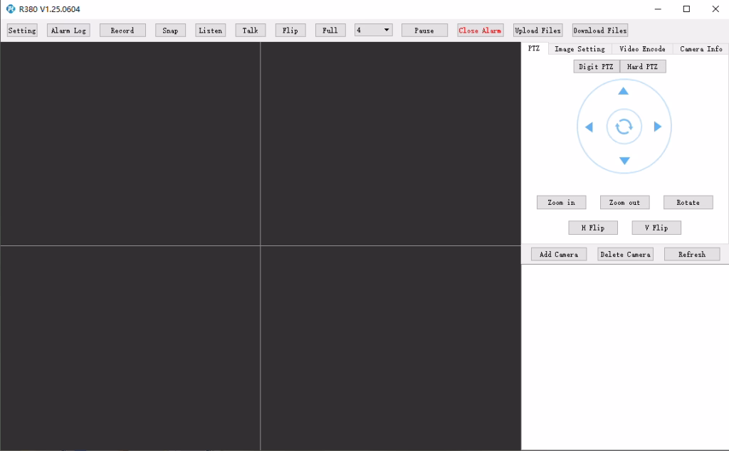
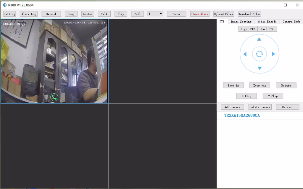
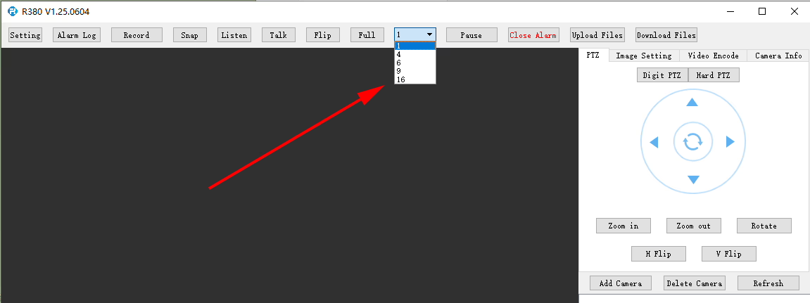
Does the R380 Player support multi-screen or simultaneous video playback?
At R380 player, it can set here.
큐: I need to connect to the LTE web UI to set up the required APN. My SIM uses a private APN and does not provide public Internet access, but it assigns a local IP address. I want to access this local IP to establish an RTSP stream from my office to a remote encoder over a 4G LTE connection. 지원되나요??
현재, this use case is not fully supported in the current firmware. APN Configuration Limitation The current firmware does not support direct user configuration of the APN through the LTE web UI or the 4G module interface. Current System Behavior In the existing design, the APN settings are managed by the main SoC, which handles the dial-up process. 결과적으로, APN configuration must be performed through our encoder module rather than directly on the LTE module itself. Network Access Consideration In your scenario, since the SIM uses a private APN without Internet access and only provides a local IP, accessing the device (예를 들어, for RTSP streaming) depends on the operator’s private network routing. This requires proper APN configuration and network-side support to enable end-to-end connectivity. Planned Improvement Our engineering team is evaluating a firmware update to add user-configurable APN support. This enhancement will provide more flexibility for private network deployments such as yours. The estimated development timeline is approximately7–10 days.
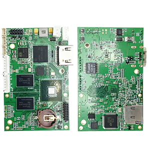
10 pcs encoder analog to digital converter
큐: How do I enable the TF card auto recording function?
에이:To enable TF card auto recording, please log in to the device’sWeb Configuration Interfaceand manually configure the recording settings.
You can follow these steps:
Open the device Web UI in your browser.
이동 설정 또는 Storage Configuration.
Find theTF 카드 녹음 옵션.
Enable or disable TF card recording as needed.
Check the TF card status and capacity information:
Confirm whether the TF card is detected correctly.
Verify the available storage capacity.
Check if the TF card status showsReadable 또는 Unformatted.
If the TF card is shown asUnformatted, please format the card before enabling recording.
메모:It is recommended to use a compatible, high-speed TF card for stable recording performance.
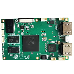
enable recording on tf card of cvbs to ip encoder board
check TF card size to see enable recording setting ok or not
질문: CVBS to IP Encoder Switches to Black-and-White After Weak Signal
I am experiencing some issues with the TO IP encoder. I am using it to convert the signal from an analog video receiver (VRX). When the signal quality is good, the image is excellent and in color. 하지만, as soon as the signal from the receiver becomes weak for a short period of time, the converter board switches to black-and-white mode, and after that it is no longer possible to restore the color image automatically. How can this issue be resolved?
답변
Thank you for your feedback. This issue is usually caused by unstable or weak CVBS video signals from the analog receiver. When the signal temporarily drops below the decoder threshold, some standard CVBS-to-IP encoder boards may lose color synchronization (PAL/NTSC chroma lock) and remain in black-and-white mode even after the signal recovers.
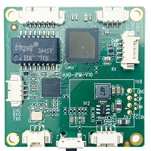
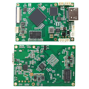
To help us confirm the exact cause, could you please send us a photo of the encoder board you are currently using?
We also recommend using our newer upgraded model, which is specially designed for weak and unstable analog video signals. It features improved low-signal locking and more stable color recovery performance.
Prevents permanent black-and-white mode after temporary signal loss
More stable operation for wireless VRX applications
Additional Suggestions
Ensure the VRX output signal level is stable
Use high-quality shielded CVBS cables
Avoid excessive cable length or power interference
Confirm that the video format (PAL or NTSC) matches the encoder settings
큐:Does the MIC pin provide bias voltage for an electret microphone, or does it expect a line-level signal? If biased, what voltage and resistor value is used?
에이:The MIC input on the V10 board supports a standard electret microphone connection.
The board provides an internal3.3V bias supplyfor the microphone input.
You donot need an external pre-amplifierfor a standard electret mic capsule.
The MIC input (AIN) is designed to connect directly to the microphone signal.
Wiring:
MIC+ → Audio input (AIN)
MIC− → GND
The biasing network is already handled internally on the board, so no external resistor calculation is required from the user side.
큐:Can you provide the exact pin assignment for the power/audio connector (VCC, GND, CVBS, 마이크, LINE_OUT)? The V10 pin label image is not clear enough.
에이:The connector uses a simple3-pin audio interface structure:
오디오 입력 (MIC IN / AIN)→ Connects to microphone input
GND→ Ground reference
오디오 출력 (LINE_OUT)→ Outputs audio signal to external amplifier or speaker system
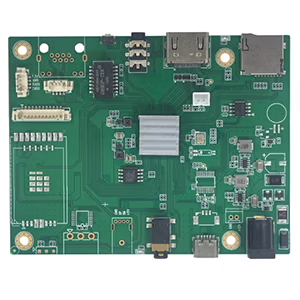
CVBS to IP video encoder audio-connector-pinout for microphone and premaplifier speaker
Functional mapping:
MIC → Audio Input (for microphone)
LINE OUT → Audio Output (to amplifier / speaker)
GND → Common ground
This design separates input and output audio paths to avoid interference and ensure stable signal transmission.
큐:What is the typical current draw at 12V?
에이:
Typical operating current at12V is approximately 130 엄마
Power consumption may vary slightly depending on:
Video input resolution (CVBS signal load)
Audio usage (마이크 / LINE OUT active or not)
Network transmission activity
Under normal operating conditions, the board remains low-power and stable for continuous use.


질문하기
응답해 주셔서 감사합니다. ✨