


พูดคุยเกี่ยวกับเพาเวอร์แอมป์ COFDM PA
COFDM PA เพาเวอร์แอมป์
ในฐานะซัพพลายเออร์มืออาชีพด้านเครื่องรับส่งสัญญาณวิดีโอและข้อมูลไร้สาย, ลูกค้าหลายรายจะถามเกี่ยวกับเพาเวอร์แอมป์เพื่อเพิ่มความครอบคลุมของเครื่องส่งสัญญาณไร้สายและเพิ่มความแรงของสัญญาณไร้สาย. เพาเวอร์แอมป์อาจกล่าวได้ว่าเป็นอุปสรรคที่วิศวกร RF หลายคนไม่สามารถหลีกเลี่ยงได้. ฟังก์ชัน, การจำแนกประเภท, ดัชนีประสิทธิภาพ, องค์ประกอบของวงจร, เทคโนโลยีการปรับปรุงประสิทธิภาพ, แนวโน้มการพัฒนา... คุณรู้ทุกสิ่งที่คุณจำเป็นต้องรู้เกี่ยวกับเพาเวอร์แอมป์ RF หรือไม่? มาทำบทเรียนกันเถอะ!
ข้อกำหนดสำคัญสองประการสำหรับ RF PA: กำลังและความเป็นเส้นตรง
ในเครื่องขยายกำลัง RF, ประสิทธิภาพพลังงาน (PAE) หมายถึงอัตราส่วนของความแตกต่างระหว่างกำลังสัญญาณเอาท์พุตและกำลังสัญญาณอินพุตต่อการใช้พลังงานของแหล่งจ่ายไฟ DC, กล่าวคือ:
เป้= (พรีฟเอาท์ - ปริฟิน)/พีดีซี = (พรีฟเอาท์ - ปริฟิน)/(VDC*ไอดีซี)
ฟังก์ชั่นของเครื่องขยายกำลัง RF RF PA
เครื่องขยายกำลังความถี่วิทยุ RF PA เป็นส่วนหลักของระบบส่งสัญญาณ, และความสำคัญของมันก็ปรากฏชัดในตัวเอง. ในวงจรปรีสเตจของเครื่องส่ง, กำลังสัญญาณ RF ที่สร้างโดยวงจรมอดูเลตออสซิลเลเตอร์มีขนาดเล็กมาก, และจะต้องผ่านขั้นตอนบัฟเฟอร์การขยายสัญญาณหลายชุด, ขั้นตอนการขยายเสียงระดับกลาง, และขั้นตอนการขยายกำลังขั้นสุดท้ายเพื่อให้ได้กำลัง RF ที่เพียงพอก่อนที่จะส่งรังสีไปยังเสาอากาศ. เพื่อให้ได้กำลังขับความถี่วิทยุที่มีขนาดใหญ่เพียงพอ, ต้องใช้เครื่องขยายกำลังความถี่วิทยุ. เพาเวอร์แอมป์มักจะมีราคาแพงที่สุด, กระหายอำนาจมากที่สุด, และส่วนประกอบที่มีประสิทธิภาพน้อยที่สุดของการติดตั้งแบบอยู่กับที่หรือเครื่องปลายทาง.
หลังจากที่โมดูเลเตอร์สร้างสัญญาณความถี่วิทยุแล้ว, สัญญาณมอดูเลตความถี่วิทยุจะถูกขยายให้มีกำลังเพียงพอโดย RFPA, ผ่านเครือข่ายที่ตรงกัน, แล้วปล่อยออกมาจากเสาอากาศ.
ฟังก์ชั่นของแอมพลิฟายเออร์คือการขยายเนื้อหาอินพุตและเอาต์พุต. อินพุตและเอาต์พุต, ที่เราเรียกว่า "สัญญาณ," มักแสดงเป็นแรงดันไฟฟ้าหรือกำลัง. สำหรับก "ระบบ" เช่นเครื่องขยายเสียง, ของมัน "ผลงาน" คือการยกระดับอะไรขึ้นมาบ้าง "ดูดซับ" และ "เอาท์พุต" สู่โลกภายนอก. นี้ "ผลงานการปรับปรุง" คือ "ความหมาย" ของการมีอยู่ของเครื่องขยายเสียง. หากเครื่องขยายเสียงสามารถมีสมรรถนะที่ดีได้, ก็สามารถมีส่วนร่วมได้มากขึ้น, ซึ่งสะท้อนถึงตัวของมันเอง "ค่า". หากมีปัญหาบางประการในเบื้องต้น "การออกแบบกลไก" ของเครื่องขยายเสียง, แล้วหลังจากเริ่มทำงานหรือทำงานมาระยะหนึ่งแล้ว, ไม่เพียงแต่จะไม่สามารถจัดหาให้ได้เท่านั้น "ผลงาน", แต่บางอย่างก็ไม่คาดคิด "กระแทก" อาจเกิดขึ้นได้. "ช็อก" เป็นหายนะต่อโลกภายนอกหรือต่อตัวเครื่องขยายเสียงเอง.
การจำแนกประเภทของเครื่องขยายกำลัง RF RF PA
ตามสภาพการทำงานที่แตกต่างกัน, เพาเวอร์แอมป์แบ่งได้ดังนี้:
ความถี่การทำงานของเครื่องขยายกำลัง RF นั้นสูงมาก, แต่ย่านความถี่ค่อนข้างแคบ. โดยทั่วไปเครื่องขยายกำลัง RF จะใช้เครือข่ายการเลือกความถี่เป็นวงจรโหลด. เพาเวอร์แอมป์ RF สามารถแบ่งสถานะการทำงานได้เป็น 3 ประเภท: ก (ก), B (B), และซี (C) ตามมุมการนำกระแสไฟฟ้า. มุมการนำไฟฟ้าของกระแสไฟของเครื่องขยายเสียง Class A คือ 360°, ซึ่งเหมาะสำหรับการขยายสัญญาณขนาดเล็กกำลังต่ำ. มุมการนำไฟฟ้าของกระแสไฟของเครื่องขยายเสียงคลาส B เท่ากับ 180°, และมุมการนำไฟฟ้าของกระแสแอมพลิฟายเออร์ Class C น้อยกว่า 180°. ทั้งคลาส B และคลาส C เหมาะสำหรับสภาพการทำงานที่มีกำลังสูง, และกำลังขับและประสิทธิภาพของสภาพการทำงานของคลาส C นั้นสูงที่สุดในบรรดาเงื่อนไขการทำงานทั้งสามประการ. เพาเวอร์แอมป์ RF ส่วนใหญ่ทำงานในคลาส C, แต่รูปคลื่นปัจจุบันของแอมพลิฟายเออร์คลาส C บิดเบี้ยวเกินไป, ดังนั้นจึงสามารถใช้เพื่อขยายกำลังโดยใช้วงจรที่ปรับแล้วเป็นโหลดเรโซแนนซ์เท่านั้น. เนื่องจากความสามารถในการกรองของลูปจูน, กระแสลูปและแรงดันไฟฟ้ายังคงใกล้เคียงกับรูปคลื่นไซน์ซอยด์โดยมีการบิดเบือนเล็กน้อย.
นอกเหนือจากสถานะการทำงานข้างต้นแล้วยังจำแนกตามมุมการนำกระแสไฟฟ้าอีกด้วย, นอกจากนี้ยังมีคลาส D (D) เครื่องขยายเสียงและคลาส E (E) แอมพลิฟายเออร์ที่ทำให้อุปกรณ์อิเล็กทรอนิกส์ทำงานในสถานะสวิตชิ่ง. ประสิทธิภาพของแอมพลิฟายเออร์คลาส D สูงกว่าแอมพลิฟายเออร์คลาส C.
ดัชนีประสิทธิภาพของเครื่องขยายกำลังความถี่วิทยุ RF PA
ตัวชี้วัดทางเทคนิคหลักของเครื่องขยายกำลังความถี่วิทยุ RF PA คือกำลังขับและประสิทธิภาพ. วิธีการปรับปรุงกำลังขับและประสิทธิภาพเป็นหัวใจสำคัญของเป้าหมายการออกแบบของเครื่องขยายสัญญาณเสียงความถี่วิทยุ. โดยปกติแล้วจะอยู่ในเครื่องขยายกำลัง RF, ความถี่พื้นฐานหรือฮาร์โมนิคบางตัวสามารถเลือกได้โดยวงจรเรโซแนนซ์ LC เพื่อให้ได้การขยายเสียงที่ไม่ผิดเพี้ยน. พูด, พูดแบบทั่วไป, พูดทั่วๆไป, อาจมีตัวบ่งชี้ต่อไปนี้ในการประเมินเครื่องขยายเสียง:
- ได้รับ. นี่คืออัตราส่วนระหว่างอินพุตและเอาต์พุต และแสดงถึงการมีส่วนร่วมของแอมพลิฟายเออร์. เครื่องขยายเสียงที่ดีก็คือการมีส่วนร่วมให้มาก "เอาท์พุต" ภายในตัวมันให้ได้มากที่สุด "หลากหลายความสามารถของตัวเอง".
-ความถี่ในการทำงาน. นี่แสดงถึงความสามารถในการรองรับของเครื่องขยายเสียงสำหรับสัญญาณความถี่ต่างๆ.
- แบนด์วิดธ์ที่ทำงาน. วิธีนี้จะกำหนดว่าแอมพลิฟายเออร์สามารถทำได้มากน้อยเพียงใด "มีส่วนช่วย". สำหรับเครื่องขยายสัญญาณย่านความถี่แคบ, แม้ว่าการออกแบบของตัวเองจะไม่มีปัญหาก็ตาม, การมีส่วนร่วมอาจถูกจำกัด.
-ความมั่นคง. ทรานซิสเตอร์ทุกตัวมีศักยภาพ "ภูมิภาคที่ไม่มั่นคง" NS "ออกแบบ" ของแอมพลิฟายเออร์จำเป็นต้องกำจัดความไม่เสถียรที่อาจเกิดขึ้นเหล่านี้. ความเสถียรของแอมพลิฟายเออร์มีสองประเภท, อาจไม่เสถียรและมั่นคงอย่างแน่นอน. แบบแรกอาจดูไม่เสถียรภายใต้เงื่อนไขและสภาพแวดล้อมบางประการ, ในขณะที่อย่างหลังสามารถรับประกันความมั่นคงได้ในทุกสถานการณ์. คำถามเรื่องความมั่นคงมีความสำคัญเนื่องจากความไม่มั่นคงหมายถึง "การสั่น", เมื่อเครื่องขยายเสียงไม่เพียงส่งผลต่อตัวมันเองเท่านั้น, แต่ยังทำให้เกิดปัจจัยที่ไม่แน่นอนอีกด้วย.
- กำลังขับสูงสุด. ตัวบ่งชี้นี้จะกำหนด "ความจุ" ของเครื่องขยายเสียง. สำหรับ "ระบบขนาดใหญ่", หวังว่าพวกเขาจะสามารถส่งออกพลังงานได้มากขึ้นโดยเสียค่าใช้จ่ายบางส่วน.
-ประสิทธิภาพ. แอมพลิฟายเออร์ต้องใช้ปริมาณที่กำหนด "พลังงาน" และยังบรรลุถึงจำนวนหนึ่งด้วย "ผลงาน". อัตราส่วนของการมีส่วนร่วมต่อการบริโภคคือประสิทธิภาพของเครื่องขยายเสียง. แอมพลิฟายเออร์ที่ดีคือแอมพลิฟายเออร์ที่มีส่วนสนับสนุนมากขึ้นและกินไฟน้อยลง.
- เป็นเส้นตรง. ความเป็นเชิงเส้นแสดงลักษณะการตอบสนองที่ถูกต้องของแอมพลิฟายเออร์ต่ออินพุตจำนวนมาก. การเสื่อมสภาพของความเป็นเส้นตรงหมายความว่าเครื่องขยายเสียง "บิดเบือน" หรือ "บิดเบือน" อินพุตเมื่อมีอินพุตเกิน. เครื่องขยายเสียงที่ดีไม่ควรแสดงสิ่งนี้ "นอกลู่นอกทาง" ธรรมชาติ.
องค์ประกอบวงจรของเครื่องขยายกำลัง RF RF PA
แอมพลิฟายเออร์มีหลายประเภท. แบบย่อ, วงจรของเครื่องขยายเสียงสามารถประกอบด้วยส่วนต่างๆ ดังต่อไปนี้: ทรานซิสเตอร์, วงจรอคติและเสถียรภาพ, และวงจรจับคู่อินพุตและเอาต์พุต.
1. ทรานซิสเตอร์
ทรานซิสเตอร์มีหลายชนิด, รวมถึงทรานซิสเตอร์ที่มีโครงสร้างต่าง ๆ ที่ถูกประดิษฐ์ขึ้น. โดยพื้นฐานแล้ว, ทรานซิสเตอร์ทำงานเป็นแหล่งกระแสหรือแรงดันไฟฟ้าที่ควบคุมโดยการแปลงพลังงานของกระแสตรงเปล่าให้เป็น a "มีประโยชน์" เอาท์พุต. พลังงานกระแสตรงได้มาจากโลกภายนอก, และทรานซิสเตอร์ก็กินมันและแปลงเป็นส่วนประกอบที่มีประโยชน์. ทรานซิสเตอร์, เราถือได้ว่าเป็น "หน่วย". แตกต่าง "ความสามารถ" ของทรานซิสเตอร์ชนิดต่างๆ, เช่นความสามารถในการต้านทานอำนาจนั้นแตกต่างกัน, ซึ่งก็เนื่องมาจากความสามารถในการรับพลังงานกระแสตรงด้วย; ตัวอย่างเช่น, ความเร็วในการตอบสนองแตกต่างกัน, ซึ่งกำหนดว่าสามารถทำงานได้กว้างและสูงแค่ไหนในย่านความถี่; ตัวอย่างเช่น, อิมพีแดนซ์ที่หันเข้าหาพอร์ตอินพุตและเอาต์พุตจะแตกต่างกัน, และความสามารถในการตอบสนองภายนอกก็แตกต่างกัน, ซึ่งกำหนดความยากในการจับคู่มัน.
2. วงจรอคติและเสถียรภาพ
วงจรไบแอสและเสถียรภาพเป็นวงจรที่แตกต่างกันสองวงจร, แต่เนื่องจากมักจะแยกแยะได้ยากและเป้าหมายการออกแบบมาบรรจบกัน, พวกเขาสามารถพูดคุยร่วมกันได้.
การทำงานของทรานซิสเตอร์จะต้องอยู่ภายใต้สภาวะอคติบางอย่าง, ซึ่งเราเรียกว่าจุดปฏิบัติการคงที่. นี่คือรากฐานของทรานซิสเตอร์และตัวมันเอง "การวางตำแหน่ง". ทรานซิสเตอร์แต่ละตัวมีตำแหน่งที่แน่นอนในตัวเอง, และตำแหน่งที่แตกต่างกันจะกำหนดโหมดการทำงานของตัวเอง, และยังมีการแสดงที่แตกต่างกันในตำแหน่งที่แตกต่างกัน. จุดวางตำแหน่งบางจุดมีความผันผวนเล็กน้อย, ซึ่งเหมาะกับงานสัญญาณขนาดเล็ก; ตำแหน่งบางจุดมีความผันผวนอย่างมาก, ซึ่งเหมาะสำหรับเอาต์พุตกำลังสูง; จุดวางตำแหน่งบางจุดมีความต้องการน้อยกว่า, การปล่อยบริสุทธิ์, และเหมาะกับงานที่มีเสียงรบกวนต่ำ; ตำแหน่งบางจุด, ทรานซิสเตอร์จะอยู่ระหว่างความอิ่มตัวและจุดตัดเสมอ, อยู่ในสถานะสลับ. จุดอคติที่เหมาะสมเป็นพื้นฐานสำหรับการทำงานตามปกติ.
วงจรรักษาเสถียรภาพจะต้องอยู่ก่อนวงจรที่ตรงกัน, เพราะทรานซิสเตอร์ต้องการวงจรรักษาเสถียรภาพเป็นส่วนหนึ่งของตัวมันเอง, แล้วติดต่อกับโลกภายนอก. ในสายตาของโลกภายนอก, ทรานซิสเตอร์ที่มีวงจรลดการสั่นไหวคือ a "ใหม่เอี่ยม" ทรานซิสเตอร์. มันทำให้แน่ใจ "การเสียสละ" เพื่อให้ได้ความมั่นคง. กลไกที่ทำให้วงจรมีเสถียรภาพทำให้ทรานซิสเตอร์ทำงานได้อย่างราบรื่นและมั่นคง.
3. วงจรจับคู่อินพุตและเอาต์พุต
วัตถุประสงค์ของวงจรจับคู่คือการเลือกโหมดที่ยอมรับ. สำหรับทรานซิสเตอร์ที่ต้องการให้เกนเพิ่มขึ้น, แนวทางคือการยอมรับและส่งออกไปทั่วกระดาน. ซึ่งหมายความว่าผ่านอินเทอร์เฟซของวงจรจับคู่, การสื่อสารระหว่างทรานซิสเตอร์ที่แตกต่างกันจะราบรื่นยิ่งขึ้น. สำหรับเครื่องขยายเสียงประเภทต่างๆ, วงจรจับคู่ไม่ใช่วิธีการออกแบบเดียวเท่านั้น "ได้รับการยอมรับอย่างครบถ้วน". ท่อขนาดเล็กบางท่อที่มี DC ขนาดเล็กและมีฐานตื้นจะเต็มใจที่จะทำการปิดกั้นจำนวนหนึ่งเมื่อรับเพื่อให้ได้ประสิทธิภาพเสียงที่ดีขึ้น. อย่างไรก็ตาม, การบล็อกไม่สามารถกระทำได้มากเกินไป, มิฉะนั้นจะส่งผลต่อการมีส่วนร่วม. สำหรับท่อส่งกำลังขนาดยักษ์บางอัน, คุณต้องระมัดระวังเมื่อส่งออก, เพราะพวกเขาไม่มั่นคงมากกว่า, และในเวลาเดียวกัน, การจองจำนวนหนึ่งช่วยให้พวกเขาออกแรงมากขึ้น "ไม่บิดเบี้ยว" พลังงาน.
การรับรู้ความเสถียรของ RF Power Amplifier RF PA
ทรานซิสเตอร์ทุกตัวอาจไม่เสถียร. วงจรรักษาเสถียรภาพที่ดีสามารถนำมาหลอมรวมกับทรานซิสเตอร์เพื่อสร้างเป็น "ทำงานอย่างต่อเนื่อง" โหมด. การนำวงจรเสถียรภาพไปใช้แบ่งได้เป็น 2 ประเภท: แถบแคบและแถบกว้าง.
วงจรป้องกันภาพสั่นไหวแบบแนร์โรว์แบนด์ใช้เกนจำนวนหนึ่ง. วงจรที่เสถียรนี้เกิดขึ้นได้จากการเพิ่มวงจรการบริโภคและวงจรเลือก. วงจรนี้อนุญาตให้ทรานซิสเตอร์สนับสนุนช่วงความถี่เพียงเล็กน้อยเท่านั้น. การรักษาเสถียรภาพบรอดแบนด์อีกประการหนึ่งคือการแนะนำข้อเสนอแนะเชิงลบ. วงจรนี้สามารถทำงานได้ในช่วงกว้าง.
แหล่งที่มาของความไม่แน่นอนคือการตอบรับเชิงบวก, และแนวคิดเรื่องความเสถียรของย่านความถี่แคบคือการควบคุมการตอบรับเชิงบวกบางส่วน. แน่นอน, สิ่งนี้ยังระงับการมีส่วนร่วมด้วย. ข้อเสนอแนะเชิงลบ, ทำได้ดี, ยังมีข้อดีที่น่าพึงพอใจอีกมากมาย. ตัวอย่างเช่น, ข้อเสนอแนะเชิงลบอาจทำให้ไม่สามารถจับคู่ทรานซิสเตอร์ได้, ไม่จำเป็นต้องจับคู่ให้เข้ากับโลกภายนอกได้ดี. นอกจากนี้, การแนะนำข้อเสนอแนะเชิงลบจะช่วยปรับปรุงประสิทธิภาพเชิงเส้นของทรานซิสเตอร์.
เทคโนโลยีการปรับปรุงประสิทธิภาพของเครื่องขยายกำลัง RF RF PA
ประสิทธิภาพของทรานซิสเตอร์มีขีดจำกัดทางทฤษฎี. ขีดจำกัดนี้จะแตกต่างกันไปตามการเลือกจุดอคติ (จุดปฏิบัติการแบบคงที่). นอกจากนี้, ถ้าวงจรต่อพ่วงไม่ได้ออกแบบมาอย่างดี, ประสิทธิภาพจะลดลงอย่างมาก. ในปัจจุบัน, วิศวกรไม่สามารถปรับปรุงประสิทธิภาพได้หลายวิธี. มีเพียงสองประเภทที่นี่: เทคโนโลยีการติดตามซองจดหมายและเทคโนโลยีโดเฮอร์ตี้.
สาระสำคัญของเทคโนโลยีการติดตามซองจดหมายคือการแยกอินพุตออกเป็นสองประเภท: เฟสและซองจดหมาย, แล้วขยายแยกตามวงจรขยายสัญญาณต่างๆ. ทางนี้, แอมพลิฟายเออร์สองตัวสามารถโฟกัสไปที่ส่วนต่างๆ ของตัวมันเองได้, และความร่วมมือของแอมพลิฟายเออร์ทั้งสองตัวสามารถบรรลุเป้าหมายของการใช้งานที่มีประสิทธิภาพสูงขึ้น.
สาระสำคัญของเทคโนโลยีโดเฮอร์ตี้คือ: โดยใช้ทรานซิสเตอร์ชนิดเดียวกันสองตัว, มีเพียงอันเดียวเท่านั้นที่ใช้งานได้เมื่ออินพุตมีขนาดเล็ก, และทำงานในสภาวะที่มีประสิทธิภาพสูง. หากอินพุตเพิ่มขึ้น, ทรานซิสเตอร์ทั้งสองทำงานพร้อมกัน. พื้นฐานสำหรับการตระหนักถึงวิธีนี้คือทรานซิสเตอร์ทั้งสองควรร่วมมือกันโดยปริยาย. สถานะการทำงานของทรานซิสเตอร์ตัวหนึ่งจะกำหนดประสิทธิภาพการทำงานของทรานซิสเตอร์ตัวอื่นโดยตรง.
ความท้าทายในการทดสอบสำหรับ RF PA
เพาเวอร์แอมป์เป็นส่วนประกอบที่สำคัญมากในระบบสื่อสารไร้สาย, แต่โดยเนื้อแท้แล้วพวกมันไม่เป็นเชิงเส้น, ทำให้เกิดปรากฏการณ์การเติบโตของสเปกตรัมที่รบกวนช่องสัญญาณที่อยู่ติดกัน, และอาจฝ่าฝืนมาตรฐานการปล่อยก๊าซเรือนกระจกนอกขอบเขตที่กำหนดตามกฎหมาย. ลักษณะนี้อาจทำให้เกิดความผิดเพี้ยนในแถบความถี่ได้, ซึ่งจะเพิ่มอัตราข้อผิดพลาดบิต (BER) และลดอัตราการส่งข้อมูลของระบบสื่อสาร.
ภายใต้อัตราส่วนกำลังสูงสุดต่อค่าเฉลี่ย (PAPR), รูปแบบการส่งสัญญาณ OFDM ใหม่จะมีกำลังสูงสุดประปรายมากขึ้น, ทำให้ PA ยากที่จะแบ่งส่วน. สิ่งนี้จะลดการปฏิบัติตามข้อกำหนดของสเปกตรัมและเพิ่ม EVM และ BER ทั่วทั้งรูปคลื่น. เพื่อแก้ไขปัญหานี้, วิศวกรออกแบบมักจะจงใจลดกำลังการทำงานของ PA. น่าเสียดาย, นี่เป็นแนวทางที่ไม่มีประสิทธิภาพมาก, เนื่องจาก PA ลดลง 10% ของกำลังการดำเนินงานและสูญเสียไป 90% ของไฟ DC.
RF PA ในปัจจุบันส่วนใหญ่รองรับหลายโหมด, ช่วงความถี่, และโหมดการมอดูเลต, ทำให้มีรายการทดสอบเพิ่มมากขึ้น. รายการทดสอบหลายพันรายการไม่ใช่เรื่องแปลก. การใช้เทคโนโลยีใหม่ๆ เช่น การลดปัจจัยหงอน (CFR), การบิดเบือนแบบดิจิตอล (DPD) และการติดตามซองจดหมาย (อีที) สามารถช่วยเพิ่มประสิทธิภาพ PA และประสิทธิภาพการใช้พลังงานได้อย่างเหมาะสม, แต่เทคโนโลยีเหล่านี้มีแต่จะทำให้การทดสอบซับซ้อนขึ้นและยืดเวลาการทดสอบออกไปอย่างมาก. เวลาออกแบบและทดสอบ. การเพิ่มแบนด์วิดท์ของ RF PA จะส่งผลให้แบนด์วิดท์ที่จำเป็นสำหรับการวัด DPD เพิ่มขึ้นห้าเท่า (อาจจะเกิน 1 GHz), เพิ่มความซับซ้อนในการทดสอบอีก.
ตามกระแสนิยม, เพื่อเพิ่มประสิทธิภาพ, ส่วนประกอบ RF PA และโมดูลส่วนหน้า (เฟม) จะได้บูรณาการกันมากขึ้น, และ FEM เดียวจะรองรับช่วงความถี่และโหมดการมอดูเลตที่กว้างขึ้น. การรวมแหล่งจ่ายไฟหรือโมดูเลเตอร์ ET เข้ากับ FEM สามารถลดความต้องการพื้นที่โดยรวมภายในอุปกรณ์เคลื่อนที่ได้อย่างมีประสิทธิภาพ. การเพิ่มจำนวนช่องตัวกรอง/ตัวพลิกหน้ากระดาษเพื่อรองรับช่วงความถี่การทำงานที่ใหญ่ขึ้นจะช่วยเพิ่มความซับซ้อนของอุปกรณ์เคลื่อนที่และจำนวนรายการทดสอบ.
โทรศัพท์มือถือ RF โมดูลเพาเวอร์แอมป์ (ปะ) สถานการณ์ตลาด
ปัจจุบันสาขาเครื่องขยายสัญญาณเสียงโทรศัพท์มือถือเป็นส่วนประกอบที่ไม่สามารถรวมเข้ากับโทรศัพท์มือถือได้. ประสิทธิภาพของโทรศัพท์มือถือ, รอยเท้า, คุณภาพการโทร, ความแรงของโทรศัพท์มือถือ, และอายุการใช้งานแบตเตอรี่ทั้งหมดจะถูกกำหนดโดยเพาเวอร์แอมป์.
การบูรณาการเพาเวอร์แอมป์ของย่านความถี่และมาตรฐานต่างๆ เหล่านี้ถือเป็นหัวข้อสำคัญที่อุตสาหกรรมกำลังศึกษาอยู่. ปัจจุบัน, มีสองวิธี: หนึ่งคือสถาปัตยกรรมฟิวชั่น, ซึ่งรวมเครื่องขยายกำลัง RF PA ของความถี่ที่แตกต่างกัน; สถาปัตยกรรมอื่นๆ คือการบูรณาการตามสายโซ่สัญญาณ, นั่นคือ, PA และตัวพลิกหน้ากระดาษถูกรวมเข้าด้วยกัน. ทั้งสองแผนมีข้อดีและข้อเสีย, และเหมาะกับมือถือรุ่นต่างๆ. สถาปัตยกรรมแบบผสมผสาน, บูรณาการสูงของ PA, มีข้อได้เปรียบด้านขนาดที่ชัดเจนมากกว่า 3 แถบความถี่, และความได้เปรียบด้านต้นทุนที่ชัดเจนสำหรับ 5-7 แถบความถี่. ข้อเสียคือถึงแม้ PA จะมีการบูรณาการ, ตัวพลิกหน้ากระดาษยังค่อนข้างซับซ้อน, และมีการสูญเสียการสลับเมื่อรวม PA, และประสิทธิภาพจะได้รับผลกระทบ. สำหรับสถาปัตยกรรมหลังนี้, ประสิทธิภาพดีขึ้น. การรวมตัวขยายกำลังและอุปกรณ์ดูเพล็กซ์เซอร์เข้าด้วยกันสามารถปรับปรุงคุณลักษณะปัจจุบันได้, ซึ่งสามารถประหยัดกระแสได้หลายสิบมิลลิแอมป์, ซึ่งเทียบเท่ากับการขยายเวลาสนทนาออกไป 15%. ดังนั้น, คนในวงการแนะนำว่าเมื่อมีมากกว่านั้น 6 แถบความถี่ (ไม่รวม 2G, หมายถึง 3G และ 4G), มีการนำสถาปัตยกรรมแบบผสมผสานมาใช้, และเมื่อน้อยกว่านั้น 4 มีการใช้คลื่นความถี่, พันธมิตรฯ, โซลูชันที่รวม PA และเครื่องดูเพล็กซ์เข้าด้วยกัน, ถูกนำมาใช้.
-
 โมดูลออปแอมป์ไฟฟ้าแรงสูงย่านความถี่กว้าง, 50วีพีพี 1เอ, ดีซี–1เมกะเฮิรตซ์, ไดร์เวอร์โหลดแบบ Capacitive ที่เสถียร
-
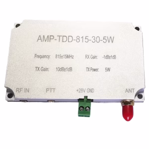
 L-Band 2W TDD โมดูลส่วนหน้า RF พร้อม PA, LNA และสวิตช์ T/R ความเร็วสูง (1100–1500 เมกะเฮิรตซ์)
ช่วงราคา: $336.00 ผ่าน $460.00
L-Band 2W TDD โมดูลส่วนหน้า RF พร้อม PA, LNA และสวิตช์ T/R ความเร็วสูง (1100–1500 เมกะเฮิรตซ์)
ช่วงราคา: $336.00 ผ่าน $460.00 -
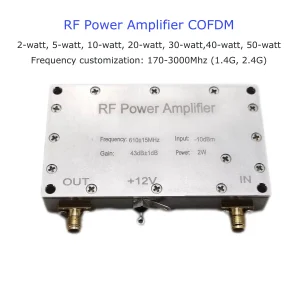
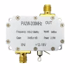 เพาเวอร์แอมป์ RF 2 โมดูลเครื่องขยายสัญญาณเครื่องส่งสัญญาณวัตต์ 200MHz
-
 2T2R TDD-1420-1530-2×5W โมดูลเครื่องขยายสัญญาณเสียง RF
ช่วงราคา: $480.00 ผ่าน $690.00
2T2R TDD-1420-1530-2×5W โมดูลเครื่องขยายสัญญาณเสียง RF
ช่วงราคา: $480.00 ผ่าน $690.00 -
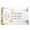 TDD 2T2R เพาเวอร์แอมป์โมดูล 1100-1500MHz | 1300M 2W 5W 10W 30W RF PA RF ส่วนหน้าโมดูล
ช่วงราคา: $460.00 ผ่าน $998.00
TDD 2T2R เพาเวอร์แอมป์โมดูล 1100-1500MHz | 1300M 2W 5W 10W 30W RF PA RF ส่วนหน้าโมดูล
ช่วงราคา: $460.00 ผ่าน $998.00 -
 เครื่องขยายความถี่วิทยุ FDD
ราคาเดิมอยู่ที่: $2,500.00.$950.00ราคาปัจจุบันอยู่ที่: $950.00.
เครื่องขยายความถี่วิทยุ FDD
ราคาเดิมอยู่ที่: $2,500.00.$950.00ราคาปัจจุบันอยู่ที่: $950.00. -
 20เครื่องขยายสัญญาณ WPA 2.4G 5.8G สำหรับลิงค์ข้อมูลโดรน
ช่วงราคา: $169.00 ผ่าน $269.00
20เครื่องขยายสัญญาณ WPA 2.4G 5.8G สำหรับลิงค์ข้อมูลโดรน
ช่วงราคา: $169.00 ผ่าน $269.00 -
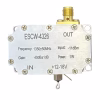 1WPA 1 วัตต์แอมพลิฟายเออร์ ESCW-4326 MCX SMA RF 12-18V 1300-1400MHz
$192.00
1WPA 1 วัตต์แอมพลิฟายเออร์ ESCW-4326 MCX SMA RF 12-18V 1300-1400MHz
$192.00