Berbicara Tentang Penguat Daya COFDM PA
Penguat Daya COFDM PA
Sebagai pemasok profesional video nirkabel dan transceiver data, banyak pelanggan akan bertanya tentang power amplifier untuk meningkatkan jangkauan pemancar nirkabel dan meningkatkan kekuatan sinyal nirkabel. Penguat daya dapat dikatakan sebagai rintangan yang tidak dapat dihindari oleh banyak insinyur RF. Fungsi, klasifikasi, indeks kinerja, komposisi sirkuit, teknologi peningkatan efisiensi, tren perkembangan... Apakah Anda mengetahui semua yang perlu Anda ketahui tentang amplifier daya RF? Ayo pelajaran make up!
Dua spesifikasi utama untuk RF PA: kekuatan dan linearitas
Dalam penguat daya RF, efisiensi daya (PAE) didefinisikan sebagai rasio perbedaan antara daya sinyal keluaran dan daya sinyal masukan terhadap konsumsi daya catu daya DC, yaitu:
PAE = (PRFOUT - PRFIN)/PDC = (PRFOUT - PRFIN)/(VDC*IDC)
Fungsi Penguat Daya RF RF PA
Radio Frekuensi Power Amplifier RF PA merupakan bagian utama dari sistem transmisi, dan pentingnya hal ini terbukti dengan sendirinya. Di sirkuit pra-tahap pemancar, daya sinyal RF yang dihasilkan oleh rangkaian osilator modulasi sangat kecil, dan perlu melalui serangkaian tahap buffer amplifikasi, tahap amplifikasi menengah, dan tahap amplifikasi daya akhir untuk mendapatkan daya RF yang cukup sebelum menyalurkan radiasi ke antena. Agar diperoleh daya keluaran frekuensi radio yang cukup besar, penguat daya frekuensi radio harus digunakan. Penguat daya seringkali merupakan yang paling mahal, paling haus kekuasaan, dan komponen instalasi stasioner atau terminal yang paling tidak efisien.
Setelah modulator menghasilkan sinyal frekuensi radio, sinyal termodulasi frekuensi radio diperkuat ke daya yang cukup oleh RFPA, melewati jaringan yang cocok, lalu dipancarkan oleh antena.
Fungsi penguat adalah untuk memperkuat isi masukan dan mengeluarkannya. Masukan dan keluaran, yang kami sebut "sinyal," sering dinyatakan sebagai tegangan atau daya. Untuk a "sistem" seperti penguat, -nya "kontribusi" adalah menaikkan level tertentu dari apa itu "menyerap" dan "keluaran" ke dunia luar. Ini "kontribusi perbaikan" adalah "arti" keberadaan amplifier. Jika amplifier dapat memiliki kinerja yang baik, maka ia dapat berkontribusi lebih banyak, yang mencerminkan dirinya sendiri "nilai". Jika ada masalah tertentu pada awalnya "desain mekanisme" dari penguat, kemudian setelah mulai bekerja atau bekerja untuk jangka waktu tertentu, bukan saja mereka tidak dapat menyediakannya "kontribusi", tapi ada pula yang tidak terduga "guncangan" mungkin terjadi. "Terkejut" merupakan bencana bagi dunia luar atau amplifier itu sendiri.
Klasifikasi Penguat Daya RF RF PA
Sesuai dengan kondisi kerja yang berbeda, penguat daya diklasifikasikan sebagai berikut:
Frekuensi operasi penguat daya RF sangat tinggi, tetapi pita frekuensinya relatif sempit. Penguat daya RF umumnya menggunakan jaringan pemilihan frekuensi sebagai rangkaian beban. Penguat daya RF dapat dibagi menjadi tiga jenis kondisi kerja: SEBUAH (SEBUAH), B (B), dan C (C) sesuai dengan sudut konduksi arus. Sudut konduksi arus penguat Kelas A adalah 360°, Yang cocok untuk amplifikasi daya rendah sinyal kecil. Sudut konduksi arus penguat Kelas B sama dengan 180°, dan sudut konduksi arus penguat Kelas C kurang dari 180°. Kelas B dan Kelas C cocok untuk kondisi kerja berdaya tinggi, dan daya keluaran serta efisiensi kondisi kerja Kelas C adalah yang tertinggi di antara ketiga kondisi kerja tersebut. Kebanyakan penguat daya RF bekerja di Kelas C, tetapi bentuk gelombang amplifier Kelas C saat ini terlalu terdistorsi, jadi mereka hanya dapat digunakan untuk memperkuat daya dengan menggunakan rangkaian yang disetel sebagai resonansi beban. Karena kemampuan penyaringan loop penyetelan, arus dan tegangan loop masih mendekati bentuk gelombang sinusoidal dengan sedikit distorsi.
Selain kondisi kerja di atas, diklasifikasikan menurut sudut konduksi arus, ada juga Kelas D (D) amplifier dan Kelas E (E) amplifier yang membuat perangkat elektronik bekerja dalam keadaan switching. Efisiensi amplifier Kelas D lebih tinggi dibandingkan amplifier Kelas C.
Indeks kinerja penguat daya frekuensi radio RF PA
Indikator teknis utama penguat daya frekuensi radio RF PA adalah daya keluaran dan efisiensi. Cara meningkatkan daya keluaran dan efisiensi adalah inti dari tujuan desain penguat daya frekuensi radio. Biasanya di penguat daya RF, frekuensi dasar atau harmonik tertentu dapat dipilih oleh rangkaian resonansi LC untuk mewujudkan amplifikasi yang tidak terdistorsi. Secara umum, mungkin ada indikator berikut dalam evaluasi amplifier:
- memperoleh. Ini adalah rasio antara masukan dan keluaran dan mewakili kontribusi penguat. Penguat yang baik adalah memberikan kontribusi sebanyak-banyaknya "keluaran" mungkin di dalamnya "jangkauan kemampuannya sendiri".
-frekuensi kerja. Ini mewakili daya dukung penguat untuk sinyal frekuensi yang berbeda.
- Bandwidth kerja. Ini menentukan seberapa jauh jangkauan amplifier "menyumbang". Untuk penguat pita sempit, padahal desainnya sendiri tidak masalah, kontribusinya mungkin terbatas.
-stabilitas. Setiap transistor mempunyai potensi "wilayah yang tidak stabil." Itu "desain" penguat perlu menghilangkan potensi ketidakstabilan ini. Ada dua jenis stabilitas penguat, berpotensi tidak stabil dan benar-benar stabil. Yang pertama mungkin tampak tidak stabil dalam kondisi dan lingkungan tertentu, sedangkan yang kedua dapat menjamin stabilitas dalam keadaan apa pun. Persoalan stabilitas penting karena artinya ketidakstabilan "osilasi", ketika amplifier tidak hanya mempengaruhi dirinya sendiri, tetapi juga menghasilkan faktor-faktor yang tidak stabil.
- Daya keluaran maksimum. Indikator ini menentukan "kapasitas" dari penguat. Untuk "sistem besar", diharapkan mereka dapat menghasilkan lebih banyak tenaga dengan mengorbankan perolehan tertentu.
-efisiensi. Amplifier harus mengkonsumsi sejumlah tertentu "energi" dan juga mencapai jumlah tertentu "kontribusi". Rasio kontribusinya terhadap konsumsi adalah efisiensi penguat. Penguat yang baik adalah yang memberikan kontribusi lebih banyak dan mengkonsumsi lebih sedikit.
- linier. Linearitas mencirikan respons penguat yang benar terhadap sejumlah besar input. Kemunduran linearitas berarti penguat "mendistorsi" atau "mendistorsi" masukan dengan adanya kelebihan masukan. Penguat yang baik seharusnya tidak menunjukkan hal ini "aneh" alam.
Komposisi Rangkaian Penguat Daya RF RF PA
Ada berbagai jenis amplifier. Sederhana, rangkaian penguat dapat terdiri dari bagian-bagian berikut: transistor, rangkaian bias dan stabilisasi, dan rangkaian pencocokan masukan dan keluaran.
1. Transistor
Transistor ada banyak macamnya, termasuk transistor dengan berbagai struktur yang telah ditemukan. Intinya, transistor bekerja sebagai sumber arus atau tegangan yang dikendalikan dengan mengubah energi arus searah kosong menjadi a "berguna" keluaran. Energi DC diperoleh dari dunia luar, dan transistor mengkonsumsinya dan mengubahnya menjadi komponen yang berguna. Sebuah transistor, kita dapat menganggapnya sebagai "sebuah unit". Berbeda "kemampuan" transistor yang berbeda, seperti kemampuan mereka menahan kekuatan berbeda-beda, yang juga karena kemampuannya memperoleh energi DC; Misalnya, kecepatan respons mereka berbeda, yang menentukan seberapa lebar dan tinggi ia dapat bekerja dalam pita frekuensi; Misalnya, impedansi yang dihadapi port input dan output berbeda, dan kemampuan respons eksternal berbeda, yang menentukan sulitnya mencocokkannya.
2. Rangkaian bias dan stabilisasi
Rangkaian biasing dan stabilisasi merupakan dua rangkaian yang berbeda, tetapi karena keduanya seringkali sulit dibedakan dan tujuan desainnya menyatu, hal-hal tersebut dapat didiskusikan bersama.
Pengoperasian transistor harus berada dalam kondisi bias tertentu, yang kami sebut titik operasi statis. Ini adalah dasar dari transistor dan miliknya sendiri "penentuan posisi". Setiap transistor memiliki posisi tertentu untuk dirinya sendiri, dan posisi yang berbeda akan menentukan mode kerjanya sendiri, dan ada juga penampilan berbeda di posisi berbeda. Beberapa titik penentuan posisi mempunyai fluktuasi kecil, yang cocok untuk pekerjaan sinyal kecil; beberapa titik posisi memiliki fluktuasi yang besar, yang cocok untuk keluaran daya tinggi; beberapa titik penentuan posisi memiliki permintaan yang lebih sedikit, pelepasan murni, dan cocok untuk pekerjaan dengan kebisingan rendah; beberapa titik penentuan posisi, Transistor selalu berada di antara saturasi dan cutoff, dalam keadaan beralih. Titik bias yang tepat adalah dasar untuk pengoperasian normal.
Rangkaian stabilisasi harus berada sebelum rangkaian pencocokan, karena transistor memerlukan rangkaian stabilisasi sebagai bagiannya sendiri, dan kemudian menghubungi dunia luar. Di mata dunia luar, transistor dengan rangkaian stabilisasinya adalah a "baru" transistor. Itu sudah pasti "pengorbanan" untuk mendapatkan stabilitas. Mekanisme yang menstabilkan rangkaian menjaga transistor berjalan lancar dan stabil.
3. Rangkaian pencocokan masukan dan keluaran
Tujuan dari rangkaian pencocokan adalah untuk memilih mode yang diterima. Bagi transistor yang ingin memberikan penguatan lebih, pendekatannya adalah menerima dan menghasilkan output secara menyeluruh. Artinya melalui antarmuka rangkaian pencocokan, komunikasi antara transistor yang berbeda lebih lancar. Untuk berbagai jenis amplifier, rangkaian pencocokan bukanlah satu-satunya metode desain "diterima secara keseluruhan". Beberapa tabung kecil dengan DC kecil dan pondasi dangkal lebih bersedia melakukan pemblokiran dalam jumlah tertentu saat menerima untuk mendapatkan kinerja kebisingan yang lebih baik. Namun, pemblokiran tidak bisa dilakukan secara berlebihan, jika tidak maka akan mempengaruhi kontribusinya. Untuk beberapa tabung listrik raksasa, Anda harus berhati-hati saat mengeluarkannya, karena mereka lebih tidak stabil, dan pada saat yang sama, sejumlah reservasi membantu mereka mengerahkan lebih banyak tenaga "tidak terdistorsi" energi.
Realisasi Stabilitas RF Power Amplifier RF PA
Setiap transistor berpotensi tidak stabil. Rangkaian penstabil yang baik dapat digabungkan dengan transistor untuk membentuk a "pekerjaan terus menerus" mode. Penerapan rangkaian stabilisasi dapat dibagi menjadi dua jenis: pita sempit dan pita lebar.
Rangkaian stabilisasi pita sempit mengkonsumsi sejumlah penguatan tertentu. Sirkuit stabil ini diwujudkan dengan menambahkan sirkuit konsumsi tertentu dan sirkuit selektif. Rangkaian ini memungkinkan transistor menyumbangkan rentang frekuensi yang kecil saja. Stabilisasi broadband lainnya adalah pengenalan umpan balik negatif. Sirkuit ini dapat bekerja dalam jangkauan yang luas.
Sumber ketidakstabilan adalah umpan balik positif, dan gagasan stabilitas pita sempit adalah untuk mengekang beberapa umpan balik positif. Tentu saja, ini juga menekan kontribusinya. Umpan balik negatif, dilakukan dengan baik, memiliki banyak keuntungan tambahan yang memuaskan. Misalnya, umpan balik negatif dapat mencegah transistor untuk dicocokkan, tidak ada yang perlu dicocokkan untuk berinteraksi dengan baik dengan dunia luar. Selain itu, pengenalan umpan balik negatif akan meningkatkan kinerja linier transistor.
Teknologi Peningkatan Efisiensi RF Power Amplifier RF PA
Efisiensi transistor memiliki batasan teoritis. Batasan ini bervariasi sesuai dengan pemilihan titik bias (titik operasi statis). Selain itu, jika sirkuit periferal tidak dirancang dengan baik, efisiensinya akan sangat berkurang. Saat ini, tidak banyak cara bagi para insinyur untuk meningkatkan efisiensi. Hanya ada dua jenis di sini: teknologi pelacakan amplop dan teknologi Doherty.
Inti dari teknologi pelacakan amplop adalah memisahkan masukan menjadi dua jenis: fase dan amplop, dan kemudian memperkuatnya secara terpisah dengan rangkaian penguat yang berbeda. Dengan cara ini, kedua amplifier dapat fokus pada bagiannya masing-masing, dan kerja sama kedua amplifier dapat mencapai tujuan pemanfaatan efisiensi yang lebih tinggi.
Inti dari teknologi Doherty adalah: menggunakan dua transistor dengan tipe yang sama, hanya satu yang berfungsi ketika inputnya kecil, dan bekerja dalam kondisi efisiensi tinggi. Jika masukan meningkat, kedua transistor bekerja secara bersamaan. Dasar dari penerapan metode ini adalah bahwa kedua transistor harus bekerja sama secara diam-diam. Keadaan kerja satu transistor akan secara langsung menentukan efisiensi kerja transistor lainnya.
Menguji Tantangan untuk RF PA
Power amplifier merupakan komponen yang sangat penting dalam sistem komunikasi nirkabel, tetapi mereka pada dasarnya non-linier, menyebabkan fenomena pertumbuhan spektral yang mengganggu saluran yang berdekatan, dan mungkin melanggar standar emisi out-of-band yang diamanatkan undang-undang. Karakteristik ini bahkan dapat menyebabkan distorsi in-band, yang meningkatkan tingkat kesalahan bit (BER) dan mengurangi kecepatan transmisi data pada sistem komunikasi.
Di bawah rasio daya puncak terhadap rata-rata (PAPR), format transmisi OFDM yang baru akan memiliki daya puncak yang lebih sporadis, membuat PA sulit untuk disegmentasi. Hal ini menurunkan kepatuhan masker spektral dan meningkatkan EVM dan BER di seluruh bentuk gelombang. Untuk mengatasi masalah ini, insinyur desain biasanya dengan sengaja mengurangi daya pengoperasian PA. Sayangnya, ini adalah pendekatan yang sangat tidak efisien, karena PA berkurang 10% dari kekuatan operasinya dan hilang 90% dari daya DC-nya.
Sebagian besar RF PA saat ini mendukung berbagai mode, rentang frekuensi, dan mode modulasi, membuat lebih banyak item tes tersedia. Ribuan item tes bukanlah hal yang aneh. Penggunaan teknologi baru seperti pengurangan faktor puncak (CFR), pradistorsi digital (DPD) dan pelacakan amplop (DAN) dapat membantu mengoptimalkan kinerja PA dan efisiensi daya, namun teknologi ini hanya akan membuat pengujian menjadi lebih rumit dan memperpanjang waktu pengujian secara signifikan. Desain dan waktu pengujian. Meningkatkan bandwidth RF PA akan menghasilkan peningkatan lima kali lipat dalam bandwidth yang diperlukan untuk pengukuran DPD (mungkin melebihi 1 GHz), semakin meningkatkan kompleksitas pengujian.
Menurut tren, untuk meningkatkan efisiensi, Komponen RF PA dan modul front-end (FEM) akan terintegrasi lebih erat, dan satu FEM akan mendukung rentang pita frekuensi dan mode modulasi yang lebih luas. Mengintegrasikan catu daya atau modulator ET ke dalam FEM dapat secara efektif mengurangi kebutuhan ruang secara keseluruhan di dalam perangkat seluler. Menambah jumlah slot filter/duplekser untuk mendukung rentang frekuensi pengoperasian yang lebih besar akan meningkatkan kompleksitas perangkat seluler dan jumlah item pengujian.
Penguat Daya Modul RF Ponsel (PA) Situasi Pasar
Bidang power amplifier ponsel saat ini merupakan komponen yang tidak dapat diintegrasikan ke dalam ponsel. Performa ponsel, tapak, kualitas panggilan, kekuatan ponsel, dan masa pakai baterai semuanya ditentukan oleh power amplifier.
Bagaimana mengintegrasikan penguat daya dengan pita frekuensi dan standar yang berbeda merupakan subjek penting yang telah dipelajari industri. Saat ini, ada dua solusi: salah satunya adalah arsitektur fusi, yang mengintegrasikan penguat daya RF PA dengan frekuensi berbeda; arsitektur lainnya adalah integrasi sepanjang rantai sinyal, yaitu, PA dan duplexer terintegrasi. Kedua skema tersebut mempunyai kelebihan dan kekurangan, dan cocok untuk ponsel yang berbeda. Arsitektur konvergen, integrasi PA yang tinggi, memiliki keunggulan ukuran yang jelas lebih dari 3 pita frekuensi, dan keuntungan biaya yang jelas untuk 5-7 pita frekuensi. Kekurangannya meskipun PA sudah terintegrasi, duplexernya masih cukup rumit, dan ada kerugian peralihan ketika PA terintegrasi, dan kinerjanya akan terpengaruh. Untuk arsitektur yang terakhir, kinerjanya lebih baik. Integrasi power amplifier dan duplexer dapat meningkatkan karakteristik arus, yang dapat menghemat arus puluhan miliampere, yang setara dengan memperpanjang waktu bicara 15%. Karena itu, orang dalam industri menyarankan bahwa ketika ada lebih dari 6 pita frekuensi (tidak termasuk 2G, mengacu pada 3G dan 4G), arsitektur konvergen diadopsi, dan ketika kurang dari 4 pita frekuensi digunakan, BANTALAN, solusi yang mengintegrasikan PA dan duplekser, digunakan.
-
 Modul Op-Amp Daya Pita Lebar Tegangan Tinggi, 50Vpp 1A, DC–1MHz, Driver Beban Kapasitif Stabil
-
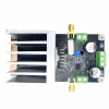
Modul Front-End RF TDD L-Band 2W dengan PA, LNA & Sakelar T/R Kecepatan Tinggi (1100–1500MHz)
Kisaran harga: $336.00 melalui $460.00
-
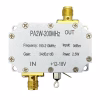
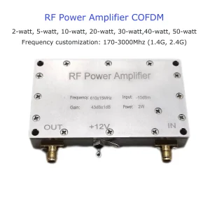
Penguat Daya RF 2 Modul penguat pemancar watt 200MHz
-
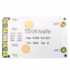
2Modul Penguat Daya RF T2R TDD-1420-1530-2×5W
Kisaran harga: $480.00 melalui $690.00
-
Modul Penguat Daya TDD 2T2R 1100-1500MHz | 1300Modul Ujung Depan RF PA RF M 2W 5W 10W 30W
Kisaran harga: $460.00 melalui $998.00
-
Penguat Frekuensi Radio FDD
Harga aslinya adalah: $2,500.00.$950.00Harga saat ini adalah: $950.00.
-
20Penguat sinyal penguat daya WPA 2.4G 5.8G untuk tautan data drone
Kisaran harga: $169.00 melalui $269.00
-
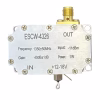
1Penguat daya WPA 1 watt ESCW-4326 MCX SMA RF 12-18V 1300-1400MHz
$192.00