


COFDM PA पावर एम्पलीफायर के बारे में बात कर रहे हैं
सीओएफडीएम पीए पावर एम्पलीफायर
वायरलेस वीडियो और डेटा ट्रांसीवर के पेशेवर आपूर्तिकर्ता के रूप में, कई ग्राहक वायरलेस ट्रांसमीटरों की कवरेज बढ़ाने और वायरलेस सिग्नल की शक्ति बढ़ाने के लिए पावर एम्पलीफायरों के बारे में पूछेंगे. पावर एम्पलीफायर को एक बाधा कहा जा सकता है जिसे कई आरएफ इंजीनियर टाल नहीं सकते हैं. समारोह, वर्गीकरण, प्रदर्शन सूचकांक, सर्किट रचना, दक्षता सुधार प्रौद्योगिकी, विकास की प्रवृत्ति... क्या आप आरएफ पावर एम्पलीफायरों के बारे में वह सब कुछ जानते हैं जो आपको जानना आवश्यक है? आओ सबक बनाओ!
आरएफ पीए के लिए दो प्रमुख विशिष्टताएँ: शक्ति और रैखिकता
आरएफ पावर एम्पलीफायरों में, शक्ति दक्षता (पीएई) इसे डीसी बिजली आपूर्ति की बिजली खपत के लिए आउटपुट सिग्नल पावर और इनपुट सिग्नल पावर के बीच अंतर के अनुपात के रूप में परिभाषित किया गया है, अर्थात्:
पीएई = (पर्फाउट - PRFIN)/पीडीसी = (पर्फाउट - PRFIN)/(वीडीसी*आईडीसी)
आरएफ पावर एम्पलीफायर आरएफ पीए के कार्य
रेडियो फ्रीक्वेंसी पावर एम्पलीफायर आरएफ पीए ट्रांसमिशन सिस्टम का मुख्य भाग है, और इसका महत्व स्वयंसिद्ध है. ट्रांसमीटर के प्री-स्टेज सर्किट में, मॉड्यूलेटिंग ऑसिलेटर सर्किट द्वारा उत्पन्न आरएफ सिग्नल शक्ति बहुत छोटी है, और इसे प्रवर्धन-बफर चरण की एक श्रृंखला से गुजरना होगा, मध्यवर्ती प्रवर्धन चरण, और एंटीना को विकिरण खिलाने से पहले पर्याप्त आरएफ शक्ति प्राप्त करने के लिए अंतिम शक्ति प्रवर्धन चरण. पर्याप्त रूप से बड़ी रेडियो फ्रीक्वेंसी आउटपुट पावर प्राप्त करने के लिए, रेडियो फ़्रीक्वेंसी पावर एम्पलीफायर का उपयोग किया जाना चाहिए. पावर एम्पलीफायर अक्सर सबसे महंगे होते हैं, सबसे अधिक सत्ता का भूखा, और किसी स्थिर संस्थापन या टर्मिनल के सबसे कम कुशल घटक.
मॉड्यूलेटर के बाद रेडियो फ्रीक्वेंसी सिग्नल उत्पन्न होता है, रेडियो फ्रीक्वेंसी मॉड्यूलेटेड सिग्नल को आरएफपीए द्वारा पर्याप्त शक्ति तक बढ़ाया जाता है, मिलान नेटवर्क से होकर गुजरा, और फिर एंटीना द्वारा उत्सर्जित किया जाता है.
एम्पलीफायर का कार्य इनपुट सामग्री को बढ़ाना और उसे आउटपुट करना है. इनपुट और आउटपुट, जिसे हम कहते हैं "सिग्नल," इन्हें अक्सर वोल्टेज या शक्ति के रूप में व्यक्त किया जाता है. एक के लिए "प्रणाली" जैसे कि एक एम्पलीफायर, इसका "योगदान" इसका एक निश्चित स्तर बढ़ाना है "अवशोषण" तथा "उत्पादन" बाहरी दुनिया के लिए. इस "सुधार योगदान" है "अर्थ" एम्पलीफायर के अस्तित्व का. यदि एम्पलीफायर का प्रदर्शन अच्छा हो सकता है, तो यह अधिक योगदान दे सकता है, जो स्वयं को दर्शाता है "कीमत". अगर शुरुआत में कुछ दिक्कतें आती हैं "तंत्र डिजाइन" एम्पलीफायर का, फिर काम शुरू करने या कुछ समय तक काम करने के बाद, इतना ही नहीं वह कुछ भी उपलब्ध नहीं करा पाएगा "योगदान", लेकिन कुछ अप्रत्याशित "झटके" तब हो सकती है. "झटका" बाहरी दुनिया या स्वयं एम्पलीफायर के लिए विनाशकारी है.
आरएफ पावर एम्पलीफायर आरएफ पीए का वर्गीकरण
विभिन्न कार्य स्थितियों के अनुसार, पावर एम्पलीफायरों को निम्नानुसार वर्गीकृत किया गया है:
आरएफ पावर एम्पलीफायरों की ऑपरेटिंग आवृत्ति बहुत अधिक है, लेकिन आवृत्ति बैंड अपेक्षाकृत संकीर्ण है. आरएफ पावर एम्पलीफायर आमतौर पर लोड सर्किट के रूप में आवृत्ति चयन नेटवर्क का उपयोग करते हैं. आरएफ पावर एम्पलीफायरों को तीन प्रकार की कार्यशील अवस्थाओं में विभाजित किया जा सकता है: ए (ए), बी (बी), और सी (सी) वर्तमान चालन कोण के अनुसार. क्लास ए एम्पलीफायर करंट का चालन कोण 360° है, जो छोटे सिग्नल कम पावर प्रवर्धन के लिए उपयुक्त है. क्लास बी एम्पलीफायर करंट का चालन कोण 180° के बराबर है, और क्लास सी एम्पलीफायर करंट का चालन कोण 180° से कम है. क्लास बी और क्लास सी दोनों उच्च-शक्ति वाली कामकाजी परिस्थितियों के लिए उपयुक्त हैं, और क्लास सी की कार्य स्थितियों की आउटपुट पावर और दक्षता तीन कार्य स्थितियों में सबसे अधिक है. अधिकांश आरएफ पावर एम्पलीफायर क्लास सी में काम करते हैं, लेकिन क्लास सी एम्पलीफायरों का वर्तमान तरंगरूप बहुत विकृत है, इसलिए उनका उपयोग केवल लोड अनुनाद के रूप में ट्यून किए गए सर्किट का उपयोग करके शक्ति को बढ़ाने के लिए किया जा सकता है. ट्यूनिंग लूप की फ़िल्टरिंग क्षमता के कारण, लूप करंट और वोल्टेज अभी भी थोड़ी विकृति के साथ साइनसॉइडल तरंगों के करीब हैं.
उपरोक्त कार्यशील अवस्थाओं के अलावा वर्तमान चालन कोण के अनुसार वर्गीकृत किया गया है, क्लास डी भी हैं (डी) एम्पलीफायरों और कक्षा ई (ए) एम्पलीफायर जो इलेक्ट्रॉनिक उपकरणों को स्विचिंग स्थिति में काम करते हैं. क्लास डी एम्पलीफायरों की दक्षता क्लास सी एम्पलीफायरों की तुलना में अधिक है.
रेडियो फ्रीक्वेंसी पावर एम्पलीफायर आरएफ पीए का प्रदर्शन सूचकांक
रेडियो फ्रीक्वेंसी पावर एम्पलीफायर आरएफ पीए के मुख्य तकनीकी संकेतक आउटपुट पावर और दक्षता हैं. आउटपुट पावर और दक्षता में सुधार कैसे किया जाए यह रेडियो फ्रीक्वेंसी पावर एम्पलीफायर के डिजाइन लक्ष्य का मूल है. आमतौर पर आरएफ पावर एम्पलीफायर में, अविरल प्रवर्धन का एहसास करने के लिए एलसी गुंजयमान सर्किट द्वारा मौलिक आवृत्ति या एक निश्चित हार्मोनिक का चयन किया जा सकता है. आम तौर पर बोलना, एम्पलीफायरों के मूल्यांकन में संभवतः निम्नलिखित संकेतक हैं:
- बढ़त. यह इनपुट और आउटपुट के बीच का अनुपात है और एम्पलीफायर के योगदान को दर्शाता है. एक अच्छा एम्प्लीफायर उतना ही योगदान देता है "उत्पादन" इसके भीतर जितना संभव हो सके "अपनी क्षमताओं की सीमा".
-काम कर आवृत्ति. This represents the carrying capacity of the amplifier for different frequency signals.
- कार्य बैंडविड्थ. This determines how much range the amplifier can "contribute". For a narrow-band amplifier, even if its own design is no problem, its contribution may be limited.
-स्थिरता. Every transistor has potential "regions of instability." NS "डिज़ाइन" of the amplifier needs to eliminate these potential instabilities. There are two types of amplifier stability, potentially unstable and absolutely stable. The former may appear unstable under certain conditions and environments, while the latter can guarantee stability under any circumstances. The question of stability is important because instability means "oscillation", when the amplifier not only affects itself, but also outputs unstable factors.
- अधिकतम उत्पादन शक्ति. This indicator determines the "capacity" एम्पलीफायर का. के लिये "big systems", यह आशा की जाती है कि वे निश्चित लाभ की कीमत पर अधिक बिजली का उत्पादन कर सकते हैं.
-क्षमता. एम्प्लीफायरों को एक निश्चित मात्रा का उपभोग करना चाहिए "ऊर्जा" और एक निश्चित मात्रा भी प्राप्त करते हैं "योगदान". खपत में इसके योगदान का अनुपात एम्पलीफायर की दक्षता है. एक अच्छा एम्प्लीफायर वह है जो अधिक योगदान देता है और कम खपत करता है.
- रेखीय. रैखिकता बड़ी संख्या में इनपुट के लिए एम्पलीफायर की सही प्रतिक्रिया को दर्शाती है. रैखिकता में गिरावट का मतलब है कि एम्पलीफायर "विकृत" या "विकृत" अतिरिक्त इनपुट की उपस्थिति में इनपुट. एक अच्छे एम्प्लीफायर को इसका प्रदर्शन नहीं करना चाहिए "अजीब" प्रकृति.
आरएफ पावर एम्पलीफायर आरएफ पीए की सर्किट संरचना
एम्प्लीफायर विभिन्न प्रकार के होते हैं. सरलीकृत, एम्पलीफायर का सर्किट निम्नलिखित भागों से बना हो सकता है: ट्रांजिस्टर, पूर्वाग्रह और स्थिरीकरण सर्किट, और इनपुट और आउटपुट मिलान सर्किट.
1. ट्रांजिस्टर
ट्रांजिस्टर कई प्रकार के होते हैं, जिसमें विभिन्न संरचनाओं वाले ट्रांजिस्टर भी शामिल हैं जिनका आविष्कार किया गया है. अनिवार्य रूप से, एक ट्रांजिस्टर एक खाली डायरेक्ट करंट की ऊर्जा को एक में परिवर्तित करके नियंत्रित करंट या वोल्टेज स्रोत के रूप में काम करता है "उपयोगी" उत्पादन. डीसी ऊर्जा बाहरी दुनिया से प्राप्त होती है, और ट्रांजिस्टर इसका उपभोग करता है और इसे उपयोगी घटकों में परिवर्तित करता है. एक ट्रांजिस्टर, हम इसे मान सकते हैं "एक इकाई". अलग "क्षमताओं" विभिन्न ट्रांजिस्टर के, जैसे कि उनकी शक्ति झेलने की क्षमता अलग-अलग होती है, जो उनकी डीसी ऊर्जा प्राप्त करने की क्षमता के कारण भी है; उदाहरण के लिए, उनकी प्रतिक्रिया की गति अलग है, जो यह निर्धारित करता है कि यह फ्रीक्वेंसी बैंड में कितना चौड़ा और ऊंचा काम कर सकता है; उदाहरण के लिए, इनपुट और आउटपुट पोर्ट के सामने आने वाली बाधाएं अलग-अलग हैं, और बाहरी प्रतिक्रिया क्षमताएं भिन्न हैं, जो इसके मिलान की कठिनाई को निर्धारित करता है.
2. Bias and stabilization circuit
Biasing and stabilization circuits are two different circuits, but because they are often difficult to distinguish and the design goals converge, they can be discussed together.
The operation of the transistor needs to be under certain bias conditions, which we call the static operating point. This is the foundation of the transistor and its own "positioning". Each transistor has a certain positioning for itself, and different positioning will determine its own working mode, and there are also different performances in different positioning. Some positioning points have small fluctuations, which are suitable for small signal work; some positioning points have large fluctuations, which are suitable for high-power output; some positioning points have less demand, pure release, and are suitable for low-noise work; some positioning points, Transistors are always hovering between saturation and cutoff, in a switching state. An appropriate bias point is the basis for normal operation.
The stabilization circuit must be before the matching circuit, because the transistor needs the stabilization circuit as part of itself, and then contacts the outside world. In the eyes of the outside world, the transistor with the stabilization circuit is a "एकदम नया" transistor. It makes certain "sacrifices" to gain stability. Mechanisms that stabilize the circuit keep the transistors running smoothly and steadily.
3. Input and output matching circuit
The purpose of the matching circuit is to select an accepted mode. For those transistors that want to provide more gain, the approach is to accept and output across the board. This means that through the interface of the matching circuit, the communication between different transistors is smoother. For different types of amplifiers, the matching circuit is not the only design method that is "accepted in its entirety". Some small tubes with small DC and shallow foundation are more willing to do a certain amount of blocking when receiving to obtain better noise performance. तथापि, the blocking cannot be overdone, otherwise it will affect its contribution. For some giant power tubes, you need to be cautious when outputting, because they are more unstable, और उस समय पर ही, a certain amount of reservation helps them to exert more "undistorted" ऊर्जा.
Realization of Stability of RF Power Amplifier RF PA
Every transistor is potentially unstable. Good stabilizing circuits can be fused with transistors to form a "continuous work" तरीका. स्थिरीकरण सर्किट के कार्यान्वयन को दो प्रकारों में विभाजित किया जा सकता है: नैरो-बैंड और वाइड-बैंड.
नैरोबैंड स्थिरीकरण सर्किट एक निश्चित मात्रा में लाभ का उपभोग करता है. इस स्थिर सर्किट को कुछ उपभोग सर्किट और चयनात्मक सर्किट जोड़कर महसूस किया जाता है. यह सर्किट ट्रांजिस्टर को केवल एक छोटी आवृत्ति रेंज में योगदान करने की अनुमति देता है. एक अन्य ब्रॉडबैंड स्थिरीकरण नकारात्मक प्रतिक्रिया की शुरूआत है. यह सर्किट एक विस्तृत रेंज पर काम कर सकता है.
अस्थिरता का स्रोत सकारात्मक प्रतिक्रिया है, और नैरो-बैंड स्थिरता का विचार कुछ सकारात्मक प्रतिक्रिया पर अंकुश लगाना है. बेशक, इससे योगदान भी दब जाता है. नकारात्मक प्रतिपुष्टि, अच्छी की, इसके कई अतिरिक्त संतुष्टिदायक लाभ हैं. उदाहरण के लिए, नकारात्मक प्रतिक्रिया ट्रांजिस्टर को मिलान करने से रोक सकती है, न ही बाहरी दुनिया के साथ अच्छी तरह से तालमेल बिठाने की जरूरत है. इसके साथ - साथ, the introduction of negative feedback will improve the linear performance of the transistor.
Efficiency Improvement Technology of RF Power Amplifier RF PA
Transistor efficiency has a theoretical limit. This limit varies with the selection of the bias point (static operating point). इसके साथ - साथ, if the peripheral circuit is not well designed, its efficiency will be greatly reduced. वर्तमान में, there are not many ways for engineers to improve efficiency. There are only two kinds here: envelope tracking technology and Doherty technology.
The essence of envelope tracking technology is to separate the input into two types: phase and envelope, and then amplify them separately by different amplifier circuits. इस प्रकार से, the two amplifiers can focus on their respective parts, and the cooperation of the two amplifiers can achieve the goal of higher efficiency utilization.
The essence of Doherty technology is: using two transistors of the same type, only one works when the input is small, and works in a high-efficiency state. If the input increases, both transistors work simultaneously. The basis for the realization of this method is that the two transistors should cooperate with each other tacitly. The working state of one transistor will directly determine the working efficiency of the other.
Testing Challenges for RF PAs
Power amplifiers are very important components in wireless communication systems, but they are inherently non-linear, causing spectral growth phenomena that interfere with adjacent channels, and may violate statutory-mandated out-of-band emission standards. This characteristic can even cause in-band distortion, which increases the bit error rate (हिट) and reduces the data transmission rate of the communication system.
Under the peak-to-average power ratio (पीएपीआर), the new OFDM transmission format will have more sporadic peak power, making the PA difficult to be segmented. This degrades spectral mask compliance and increases EVM and BER across the waveform. To solve this problem, design engineers usually deliberately reduce the operating power of the PA. Unfortunately, this is a very inefficient approach, since the PA reduces 10% of its operating power and loses 90% of its DC power.
Most of today's RF PAs support multiple modes, आवृत्ति रेंज, and modulation modes, making more test items available. Thousands of test items are not uncommon. The use of new technologies such as crest factor reduction (सीएफआर), digital predistortion (डीपीडी) and envelope tracking (ET) can help optimize PA performance and power efficiency, but these technologies will only make the test more complicated and greatly prolong the test time. Design and test time. Increasing the bandwidth of the RF PA will result in a five-fold increase in the bandwidth required for DPD measurements (possibly exceeding 1 गीगा), further increasing test complexity.
According to the trend, in order to increase efficiency, RF PA components and front-end modules (FEM) will be more closely integrated, and a single FEM will support a wider range of frequency bands and modulation modes. Integrating an ET power supply or modulator into the FEM can effectively reduce the overall space requirements inside the mobile device. Increasing the number of filter/duplexer slots to support a larger operating frequency range will increase the complexity of mobile devices and the number of test items.
Mobile Phone RF Module Power Amplifier (देहात) Market Situation
The field of mobile phone power amplifiers is currently a component that cannot be integrated in mobile phones. Mobile phone performance, footprint, call quality, mobile phone strength, and battery life are all determined by the power amplifier.
How to integrate these power amplifiers of different frequency bands and standards is an important subject that the industry has been studying. वर्तमान में, there are two solutions: one is the fusion architecture, which integrates RF power amplifiers PA of different frequencies; the other architecture is the integration along the signal chain, वह है, the PA and the duplexer are integrated. Both schemes have advantages and disadvantages, and are suitable for different mobile phones. Converged architecture, high integration of PA, has obvious size advantage for more than 3 आवृत्ति बैंड, and obvious cost advantage for 5-7 आवृत्ति बैंड. The disadvantage is that although the PA is integrated, the duplexer is still quite complicated, and there is switching loss when the PA is integrated, and the performance will be affected. For the latter architecture, the performance is better. The integration of the power amplifier and the duplexer can improve the current characteristics, which can save tens of milliamperes of current, which is equivalent to extending the talk time by 15%. इसलिये, industry insiders suggest that when there are more than 6 आवृत्ति बैंड (excluding 2G, referring to 3G and 4G), a converged architecture is adopted, and when less than 4 frequency bands are used, PAD, a solution integrating PA and duplexer, is used.
-
 हाई वोल्टेज वाइडबैंड पावर ऑप-एम्प मॉड्यूल, 50वीपीपी 1ए, डीसी-1मेगाहर्ट्ज, स्थिर कैपेसिटिव लोड ड्राइवर
-
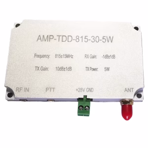
 पीए के साथ एल-बैंड 2डब्ल्यू टीडीडी आरएफ फ्रंट-एंड मॉड्यूल, LNA & High-Speed T/R Switch (1100-1500 मेगाहर्ट्ज)
मूल कीमत थी: $750.00.$350.00वर्तमान कीमत है: $350.00.
पीए के साथ एल-बैंड 2डब्ल्यू टीडीडी आरएफ फ्रंट-एंड मॉड्यूल, LNA & High-Speed T/R Switch (1100-1500 मेगाहर्ट्ज)
मूल कीमत थी: $750.00.$350.00वर्तमान कीमत है: $350.00. -
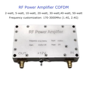
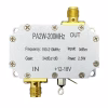 आरएफ पावर एम्पलीफायर 2 वाट्स 200 मेगाहर्ट्ज ट्रांसमीटर एम्पलीफायर मॉड्यूल
-
 2T2R TDD-1420-1530-2×5W आरएफ पावर एम्पलीफायर मॉड्यूल
मूल्य सीमा: $480.00 के माध्यम से $690.00
2T2R TDD-1420-1530-2×5W आरएफ पावर एम्पलीफायर मॉड्यूल
मूल्य सीमा: $480.00 के माध्यम से $690.00 -
 TDD 2T2R पावर एम्पलीफायर मॉड्यूल 1100-1500MHz | 1300एम 2डब्ल्यू 5डब्ल्यू 10डब्ल्यू 30डब्ल्यू आरएफ पीए
मूल्य सीमा: $466.00 के माध्यम से $998.00
TDD 2T2R पावर एम्पलीफायर मॉड्यूल 1100-1500MHz | 1300एम 2डब्ल्यू 5डब्ल्यू 10डब्ल्यू 30डब्ल्यू आरएफ पीए
मूल्य सीमा: $466.00 के माध्यम से $998.00 -
 एफडीडी रेडियो फ्रीक्वेंसी एम्पलीफायर
मूल कीमत थी: $2,500.00.$950.00वर्तमान कीमत है: $950.00.
एफडीडी रेडियो फ्रीक्वेंसी एम्पलीफायर
मूल कीमत थी: $2,500.00.$950.00वर्तमान कीमत है: $950.00. -
 20ड्रोन डेटा लिंक के लिए WPA 2.4G 5.8G पावर एम्पलीफायर सिग्नल बूस्टर
मूल्य सीमा: $169.00 के माध्यम से $269.00
20ड्रोन डेटा लिंक के लिए WPA 2.4G 5.8G पावर एम्पलीफायर सिग्नल बूस्टर
मूल्य सीमा: $169.00 के माध्यम से $269.00 -
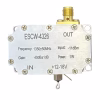 1WPA 1-वाट पावर एम्पलीफायर ESCW-4326 MCX SMA RF 12-18V 1300-1400MHz
$192.00
1WPA 1-वाट पावर एम्पलीफायर ESCW-4326 MCX SMA RF 12-18V 1300-1400MHz
$192.00