-
×
 ໂມດູນ Demodulation ກັບ TS stream output dvb-t dvb-t2 siano chipset SMS4470
2 × $55.00
ໂມດູນ Demodulation ກັບ TS stream output dvb-t dvb-t2 siano chipset SMS4470
2 × $55.00 -
×
 AI IPC Rockchip RV1126 IMX415 Sony Lens camera sensor board module SDK software developmentkit MIPI IP USB
1 × $166.00
AI IPC Rockchip RV1126 IMX415 Sony Lens camera sensor board module SDK software developmentkit MIPI IP USB
1 × $166.00 -
×
 ເຄື່ອງຮັບ DVB-T COFDM 900 902 928 930ເຄື່ອງຮັບສາຍສົ່ງວິດີໂອໄຮ້ສາຍ Mhz
1 × $139.00
ເຄື່ອງຮັບ DVB-T COFDM 900 902 928 930ເຄື່ອງຮັບສາຍສົ່ງວິດີໂອໄຮ້ສາຍ Mhz
1 × $139.00 -
×
 Rockchip RV1126 core board IPC AI ໂມດູນການພັດທະນາ Artificial Intelligence PCBA
1 × $79.00
Rockchip RV1126 core board IPC AI ໂມດູນການພັດທະນາ Artificial Intelligence PCBA
1 × $79.00


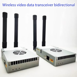
ໂມດູນຮັບສັນຍານວິທະຍຸຕາຂ່າຍ IP ສໍາລັບການເຊື່ອມຕໍ່ຂໍ້ມູນວິດີໂອ drone UHF Vcan2024
IP mesh radio transceiver module for drone video data link UHF
IP mesh radio transceiver module is suitable for point-to-multi-point or multi-point-to-multi-point network requirements.
ຍົກຕົວຢ່າງ, your project requires multiple transmitters and multiple receivers. Each node can act as a relay for other nodes. Each node cannot be individually defined as a transmitter, ຮັບ, or repeater. Each node is a transmitter, a receiver, and a repeater. Such as security squads, bicycle racing, 2+ drones in the sky and 2+ receivers on the ground, ແລະຄໍາຮ້ອງສະຫມັກອື່ນໆ.

ສາລະບານ
ຄຸນນະສົມບັດ
- Two-way bidirectional transmission video data download and upload
- TDD OFDM full-duplex IP Mesh radio wireless transceiver module for video and data transmission
- Dual RF Power: 24±1dBm, 2-ຊ່ອງ
- Optional Working Frequency: 566~678MHz (112Mhz range hopping), 1420~1530MHz (110Mhz range hopping)
- Three Ethernet RJ45 for video or data and One RS232 UART data link, ຄວບຄຸມ UART (TTL) ພອດ
- Support transmit distance: 500~2000 meters (ຮູບແບບນີ້ຖືກອອກແບບມາສໍາລັບການຖ່າຍທອດວິດີໂອແລະຂໍ້ມູນໄຮ້ສາຍທີ່ມີການເຊື່ອມຕໍ່ຂໍ້ມູນໄຮ້ສາຍສອງທາງ), 5~22km (ຮູບແບບນີ້ຖືກອອກແບບມາສໍາລັບການຖ່າຍທອດວິດີໂອແລະຂໍ້ມູນໄຮ້ສາຍທີ່ມີການເຊື່ອມຕໍ່ຂໍ້ມູນໄຮ້ສາຍສອງທາງ); For a longer range, we needed the extra power amplifier support. (2ວັດ, 5ວັດ, 10ວັດ)
- This board supports the CX6779K modem.

FHSS Frequency Hopping
- We designed this wireless video and data transmission with uplink and downlink for those who need the frequency automatic hopping function.
- With frequency hopping technology (ຮູບແບບນີ້ຖືກອອກແບບມາສໍາລັບການຖ່າຍທອດວິດີໂອແລະຂໍ້ມູນໄຮ້ສາຍທີ່ມີການເຊື່ອມຕໍ່ຂໍ້ມູນໄຮ້ສາຍສອງທາງ) to ensure better stable signal communication, when the current frequency signal is worse, the system will automatically change the working frequency to another frequency for a better signal.
- This bidirectional OFDM radio module can work from 566Mhz to 678MHz or from 1420Mhz to 1530MHz bandwidth. So the frequency range has 110Mhz bandwidth change or hopping. If you set the frequency bandwidth at 10 MHz, then there are 11 frequency points for hopping.
ຂໍ້ມູນ
- ຮູບແບບນີ້ຖືກອອກແບບມາສໍາລັບການຖ່າຍທອດວິດີໂອແລະຂໍ້ມູນໄຮ້ສາຍທີ່ມີການເຊື່ອມຕໍ່ຂໍ້ມູນໄຮ້ສາຍສອງທາງ (Need FDD COFDM model?)
- Supports 2 Frequency ranges (566~678MHz/1420~1530MHz)
- Supports FHSS frequency automatic hopping function
- 4/3/5/10/20/40ຮູບແບບນີ້ຖືກອອກແບບມາສໍາລັບການຖ່າຍທອດວິດີໂອແລະຂໍ້ມູນໄຮ້ສາຍທີ່ມີການເຊື່ອມຕໍ່ຂໍ້ມູນໄຮ້ສາຍສອງທາງ
- Max 100Mbps throughput
- Dual RF transmission power: 24±1dBm, 2-channel for uplink and downlink
- constellation: QPSK, 16QAM, 64QAM, ຮູບແບບນີ້ຖືກອອກແບບມາສໍາລັບການຖ່າຍທອດວິດີໂອແລະຂໍ້ມູນໄຮ້ສາຍທີ່ມີການເຊື່ອມຕໍ່ຂໍ້ມູນໄຮ້ສາຍສອງທາງ
- ທີ່ລະອຽດອ່ອນ: -95dBm (20ວາງຂອງສັນຍານ MHz)
- Supports IP Video Data Transmission (3 ພອດ Ethernet)
- ຮູບແບບນີ້ຖືກອອກແບບມາສໍາລັບການຖ່າຍທອດວິດີໂອແລະຂໍ້ມູນໄຮ້ສາຍທີ່ມີການເຊື່ອມຕໍ່ຂໍ້ມູນໄຮ້ສາຍສອງທາງ (1X RS232, 1X TTL)
- Without extra PA, Up to 22km LOS (ຮູບແບບນີ້ຖືກອອກແບບມາສໍາລັບການຖ່າຍທອດວິດີໂອແລະຂໍ້ມູນໄຮ້ສາຍທີ່ມີການເຊື່ອມຕໍ່ຂໍ້ມູນໄຮ້ສາຍສອງທາງ) ແລະ 2 ກິໂລແມັດ LOS(ຮູບແບບນີ້ຖືກອອກແບບມາສໍາລັບການຖ່າຍທອດວິດີໂອແລະຂໍ້ມູນໄຮ້ສາຍທີ່ມີການເຊື່ອມຕໍ່ຂໍ້ມູນໄຮ້ສາຍສອງທາງ)
- Can add 2watts, 5ວັດ, ຫຼື 10 watts to support longer range
- Web UI and control UART for management
- ການເຂົ້າລະຫັດ AES128
- ການຄວບຄຸມການຖ່າຍທອດ Uplink ແລະ downlink (Video stream needs more and data streaming needs less)
- ຮູບແບບເຄືອຂ່າຍ: One-to-one P2P, one-to-many P2MP, many-to-one MP2P, relay/repeater, mesh or swarm network。
- ການນໍາໃຊ້ພະລັງງານ: <7W
- ຂະຫນາດ: 80 x 57 x 9.1mm
- ນ້ໍາ: 41g
- Working Temperate: -20℃ ~ +65 ℃
- Storage Temperate: -40℃ ~ +80 ℃
IP Radio Module Connector (ການປ້ອນຂໍ້ມູນ / ຜົນໄດ້ຮັບທີ)
| ພະລັງງານໃນ | 2PIN PH2.0mmConnector, DC ໃນ:9~30V |
| Ethernet, 1 | 4ຕົວເຊື່ອມຕໍ່ PIN PH1.25mm |
| Ethernet, 2 | 4ຕົວເຊື່ອມຕໍ່ PIN PH1.25mm |
| Ethernet-3 | 4ຕົວເຊື່ອມຕໍ່ PIN PH1.25mm |
| UART Data | 3ຕົວເຊື່ອມຕໍ່ PIN PH1.25mm, RS232(or TTL 3.3V) |
| Control UART | 3ຕົວເຊື່ອມຕໍ່ PIN PH1.25mm, TTL 3.3V |
| USB | Micro USB Connector, ສໍາລັບການຍົກລະດັບຊອບແວ |
| ສະຫຼັບ | Tx/Rx control signal for outside power amplifier |
| ເສົາອາກາດຫຼັກ | ຜອດເສົາອາກາດ Tx/Rx, IPEX |
| ເສົາອາກາດທີສອງ | ຜອດເສົາອາກາດ Tx/Rx, IPEX |
| 12V ອອກ | On-board ອອກ 12V(<200mA), ສໍາລັບການສະຫນອງພະລັງງານພັດລົມເຢັນ |
ອີເທີເນັດ1, Ethernet2 and Ethernet3
The three Ethernet ports on board are bridged connections, so their IP addresses are the same. The photo below shows the 4PIN signals of the Ethernet port.

Switch Port
This port is a TX transmitter / RX receiver control signal for the extra power amplifier. The maximum RF transmission power of our module is 24±1dBm two channels, We also provide the correct power amplifier to increase the RF Power to 2-watt / 5-watt /10-watt if you need a longer range than 22km.
The below diagram shows how to add a power amplifier outside extra of this IP Radio Module.

This operation is for your reference only. If you need to add an external power amplifier, it is best to tell us and we will configure it for you, or ask a professional to operate it, ຖ້າບໍ່ດັ່ງນັ້ນ, the PA will be easily burned.
| ສັນຍານ | Electrical level | I/O | ຄໍາອະທິບາຍ | mark |
| PA-enable1 | 1.8V | ການ | High electrical level: data transmitting, change to high electrical level at 3.19us before transmitting and to low electrical level at 0.26us after transmitting finished. | High-Tx
Low-Rx |
UART Data
- The data UART is RS232 as default.
- We also can change the data port from RS232 to TTL 3.3V UART before the cargo delivery.
- The baud rate of data UART can be set as 115200, 57600, 38400, 19200, 9600, 4800, 2400, ແລະ 1200.

how the data UART works at the wireless transmission of the IP MESH radio Module
Control UART and USB port
Only one of these two ports is valid at the same time. Control UART is valid by default shipment. Please contact us if you need to use a USB UART. You can manage our module with Web UI or AT command via control UART.
LEDs light
LED1: ພະລັງງານ LED, ສີແດງ, ແສງສະຫວ່າງໂດຍປົກກະຕິ.
LED2: blue, LED3: ສີຂຽວ, LED2 and LED3 indicate the wireless working status as described in the below table.
| Central node | Blue LED2 light on all the time and green LED3 is not light |
| Access node | Green LED3 light on all the time when the access node is connected with the central node. |
| The blue LED2 indicate the access node linking signal status with the central node.
When the wireless linking signal is strong, blue LED2 blinks every 30 ວິນາທີ; When the wireless linking signal is middle, blue LED2 blinks every 6 ວິນາທີ; When the wireless linking signal is weak, blue LED2 blinks every 1 ທີສອງ. |
Sometimes customers may need to assemble the indicating LEDs on their housing case panel, so our board also provides a soldering hole for the three LED signals. The LED signal is described in the below table.
| ໄຟ LED | ຄໍາອະທິບາຍ | Representation soldering hole |
| LED1 | ພະລັງງານ LED | LED1-GND and LEDs-VCC |
| LED2 | Wireless indicating LED | LED2-GND and LEDs-VCC |
| LED3 | LED3-GND and LEDs-VCC |
Wireless networking with the IP MESH Radio Module
- Our module supports two operating modes: ພອດເສົາອາກາດ Rx. It can be managed through Web UI or AT command via control UART.
- Our module supports features of a maximum of 63 ພອດເສົາອາກາດ Rx. All the Nodes are in the same wireless LAN and share the whole transmission bandwidth (maximum 100Mbps throughout).
- Data from the Central Node to the Access Node, ພອດເສົາອາກາດ Rx, and data from the Access Node to the Central Node, ພອດເສົາອາກາດ Rx.
- ອັດຕາສ່ວນການຖ່າຍທອດ Uplink ແລະ downlink ສາມາດຄວບຄຸມໄດ້ໂດຍຜ່ານ UI ເວັບ ຫຼືຄໍາສັ່ງ AT.
- When using Our module for Point-to-Point transmitting, uplink ແລະ downlink ແບ່ງປັນແບນວິດການສົ່ງທັງຫມົດ (maximum 100Mbps throughout) ຄືກັນ.
- Our module supports networking modes: ຈຸດຕໍ່ຈຸດ, Point-to-Multi-point, Relay, ແລະຕາຫນ່າງ (specify mesh version when ordering).

MESH Centerless Networking


ການທົບທວນຄືນ
ມີຄວາມຄິດເຫັນທີ່ບໍ່ມີ.