


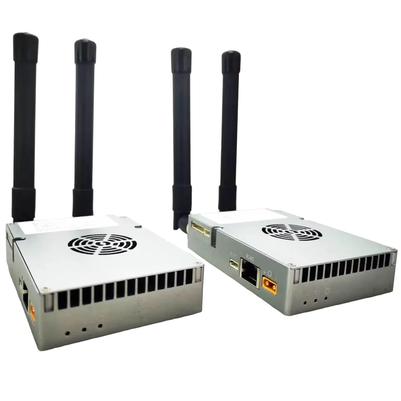
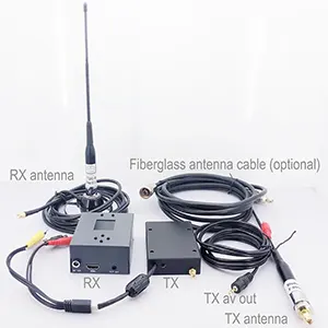


I need to connect the Ethernet switch to the transmitter using an Ethernet cable. See the picture below. The transmitter only has 4 points for Ethernet: T+ T- R+ R-. Ale 8 cables in CAT6. Please ask the engineer to tell me which four to use based on color
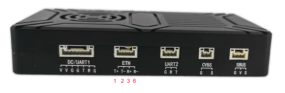
Zkontrolujte prosím níže uvedený obrázek.
T+: Ne. 1 Orange/White
T-: Ne. 2 oranžový
RX+: Ne. 3 Green/White
RX-: Ne. 6 Zelený
Ethernet Cable Color Pin Definition for Wireless Video Transmitter and Receiver
When connecting a wireless video transmitter to an Ethernet switch, it is important to understand the pin configuration and how it relates to the standard Ethernet cable wiring. Most standard Ethernet cables, such as CAT5, CAT5e, or CAT6, consist of eight individual wires grouped in four twisted pairs. Each wire has a specific color code and is used for transmitting or receiving data signals.
In a standard RJ45 Ethernet connector, the wire pairs are typically assigned as follows:
- Pair 1: Orange/White and Orange
- Pair 2: Green/White and Green
- Pair 3: Blue/White and Blue
- Pair 4: Brown/White and Brown
nicméně, some wireless video transmitters, particularly professional models, do not require all eight wires for communication. Místo toho, they operate on a 2-pair Ethernet configuration, using only four wires for differential transmit (TX) a přijímat (RX) signály. The remaining four wires are not used in this configuration.
For your wireless video transmitter, the Ethernet interface has only four points labeled T+, T-, R+, and R-, which correspond to transmit positive, transmit negative, receive positive, and receive negative, resp. Based on the engineer’s instructions and standard Ethernet wiring conventions, the connections should be made as follows:
- T+ (Transmit Positive): Kolík 1 – Orange/White
- T- (Transmit Negative): Kolík 2 – Orange
- R+ (Receive Positive): Kolík 3 – Green/White
- R- (Receive Negative): Kolík 6 – Green
This means that when you are using a CAT6 Ethernet cable to connect the transmitter to an Ethernet switch, you only need to use four of the eight wires, specifically the two pairs responsible for transmit and receive. The other two pairs (Blue/White & Modrý, Brown/White & Hnědý) are not connected and remain unused.
Step-by-Step Connection Instructions:
- Prepare the Ethernet Cable: Strip the outer insulation carefully without damaging the inner wires. Separate the four wires needed for connection: Orange/White, oranžový, Green/White, and Green.
- Verify Transmit and Receive Wires: Confirm that Orange/White and Orange are used for transmitting data from the transmitter, while Green/White and Green are used for receiving data.
- Connect to the Transmitter: Solder or insert the wires into the transmitter’s Ethernet pins according to the mapping:
- Kolík 1: Orange/White → T+
- Kolík 2: Orange → T-
- Kolík 3: Green/White → R+
- Kolík 6: Green → R-
- Connect to the Ethernet Switch: On the switch side, use standard Ethernet wiring to connect the cable. Most switches automatically detect which wires are used for data transmission, so the 2-pair connection will operate correctly without any additional configuration.
- Test the Connection: Once the wires are connected, power on the transmitter and switch to verify network communication. Use a network testing tool or monitor the transmitter for proper link status.
Důležité poznámky:
- Using only the specified four wires ensures compatibility with the transmitter’s 2-pair Ethernet interface.
- Do not attempt to connect additional pairs (Blue/White & Modrý, Brown/White & Hnědý), as these are unused in this configuration.
- Make sure to maintain proper pairing (Twisted Pair) to minimize crosstalk and signal interference. Orange/White & Orange and Green/White & Green must remain twisted pairs.
- Proper termination and secure connections are crucial to maintain signal integrity, especially for high-bandwidth wireless video transmission.
By following this color-coded pin definition and wiring method, you can reliably connect your wireless video transmitter to an Ethernet switch using a standard CAT6 cable, ensuring stable and efficient network communication. This configuration is commonly used in professional wireless video transmission systems where the transmitter and receiver operate over Ethernet interfaces with minimal wiring.
Položit otázku
Děkujeme za Vaši odpověď. ✨