


Digital Down Converter
Wireless Video Transmission RF Frequency Digital Down Converter COFDM Transfer frequency 2.4G to 600Mhz low

Table of Contents
Punkty sprzedaży
- Input frequencies from 24000 to 600MHz (Lower 1800Mhz)
- Wysoka przepustowość
- Low phase noise
- High-frequency stability

Specyfikacja
RF Frequency Range: 2400 Mhz
IF Frequency Range: 600 Mhz
Strata zwrotu:-12 dB
Frequency Accuracy: ±10 ppm
Odrzucenie obrazu: 60 dBc
Płaskość: ±0.5 dB (8Szerokość pasma MHz)
Conversion Gain: 25 dB
Phase Noise (dBc/Hz)
dBc/Hz@1KHz ≤-80
dBc/Hz@10KHz ≤-90
dBc/Hz@100KHz ≤-100
Napięcie zasilania: 10~15V
Power Current: 100 mama
Operating Temperature Range: +25 ℃

Port
RF IN: SMA-50K
IF OUT: SMA-50K
Power +12V: Stick
GND: Soldering lug
Notatka
- The converter does not need to add a low-noise amplifier at the back end.
- Actual Test: closed-loop test under the frequency of 2.4GHz/bandwidth 4MHz, the receiving sensitivity can reach -105dBm.
- Input frequency supports 1~3GHz. (We can help customize).
- Output frequency supports 300~700MHz. (We can support customize).

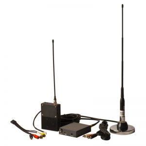
About the above video:
Our most popular products are wireless video transmitters and receivers. Jednakże, some clients require modification of the transmission frequency to meet local legal demand, in which case the digital frequency up-down converter block comes in handy. One customer requested that we customize the RF frequency down converter for his 2.4G wireless video transmitter. So the input frequency is 2.4GHz, the output frequency is 600MHz, and the lowdown frequency is 1800MHz. We created the sample in accordance with his specifications. So I showed him a simple video that showed the 2.4G transmitter and 600Mhz receiver working correctly. If you have a similar requirement, such as 1-3G frequency input and 300-700Mhz output, please contact us for a custom solution.


Często zadawane pytania
Konwerter obniżający blok częstotliwości RF (BDC) do bezprzewodowych nadajników wideo to urządzenie, które może przekształcić zakres wysokich częstotliwości na zakres niskich częstotliwości.
Zwykle używany po stronie bezprzewodowego nadajnika wideo. Na przykład,
- Konwerter w dół z 5,8G na 2,4G
- Konwerter w dół z 2,4G na 1,2G
- Konwerter w dół z 1,2G na 600 MHz
Wynika to z faktu, że częstotliwości transmisji bezprzewodowej w wielu krajach lub regionach są ograniczone lokalnymi przepisami i regulacjami.
Niedozwolone jest używanie w określonym zakresie częstotliwości.
Aby zmienić częstotliwość roboczą nadajnika i odbiornika, wymagana jest konwersja w dół lub w górę. Upewnij się, że częstotliwość transmisji jest zgodna z lokalnymi przepisami i regulacjami.
Zdarza się również, że profesjonalna częstotliwość odbioru jest stała, Na przykład, pomiędzy 300-800 MHz.
W celu sparowania częstotliwości nadajnika, TNależy zmniejszyć częstotliwość nadajnika 1,2G.
Wszystko to wymaga zastosowania konwertera obniżającego częstotliwość do bezprzewodowej transmisji wideo.
Yes, odpowiedział nasz profesjonalny inżynier, możemy to zrobić. I, przed dostawą, pokażemy Ci film testowy.
Yes, nasz profesjonalny inżynier potwierdza, że możemy w tym celu przeprojektować i zmodyfikować niektóre kluczowe komponenty. Jasne, przed dostawą, pokażemy Ci film testowy.
Dziękujemy za zapytanie, Sprawdzę to u naszego inżyniera.
Dziękujemy za zapytanie. Możemy dostosować dla Ciebie.
Podaj nam szczegóły specyfikacji modułów nadajnika i odbiornika.
Pytanie: Jesteśmy zainteresowani konwerterem downconverter n.1 z 950-1500 Mhz do 350-850 Konwerter w górę MHz i nr 1 z 350-850 Mhz do 950-1500 Mhz. Lokalny oscylator 1800 Mhz.
Yes, Oto nasza specyfikacja dla Twoich referencji.
Arkusz specyfikacji bloku konwertera częstotliwości
|
Przedmiot |
Specyfikacja |
|
częstotliwość wejściowa |
950 MHz ~ 1550 MHz |
|
częstotliwość wyjściowa |
350 MHz ~ 850 MHz |
|
Częstotliwość lokalna |
1800 MHz |
|
PRZĘSŁO |
500MHz |
|
Liczba szumów |
≤1,5 dB |
|
osiągać |
25 dB |
|
Wyciek nośnika |
≤-20 dBm |
|
Nierówność paska(8MHz) |
≤1,5 dB |
|
IP3: |
≥15dBm |
|
maksymalny poziom wejściowy |
-10dBm |
|
VSWR |
≤1,5 |
|
temperatura pracy |
-10~+60 ℃ |
|
prąd napięciowy |
12V/240mA |
|
Interfejs RF |
SMA-50KFD |
|
rozmiar |
108*48*15mm |
|
Tryb zasilania |
Zasilanie gniazda |

Arkusz specyfikacji bloku konwertera częstotliwości
|
Przedmiot |
Specyfikacja |
|
częstotliwość wejściowa |
350 MHz ~ 850 MHz |
|
częstotliwość wyjściowa |
950 MHz ~ 1550 MHz |
|
Częstotliwość lokalna |
1800 MHz |
|
PRZĘSŁO |
500MHz |
|
Liczba szumów |
≤1,5 dB |
|
osiągać |
25 dB |
|
Wyciek nośnika |
≤-20 dBm |
|
Nierówność paska(8MHz) |
≤1,5 dB |
|
IP3: |
≥15dBm |
|
maksymalny poziom wejściowy |
-10dBm |
|
VSWR |
≤1,5 |
|
temperatura pracy |
-10~+60 ℃ |
|
prąd napięciowy |
12V/240mA |
|
Interfejs RF |
SMA-50KFD |
|
rozmiar |
108*48*15mm |
|
Tryb zasilania |
Zasilanie gniazda |
Pytanie: Jeżeli sygnał -25 dbm wejdź, jaki poziom ma wyjście coverterd?
Odpowiedź: 0 dBm
Nie możemy dokonać konwersji w górę częstotliwości 1.0-2.5 GHz do 5.8 GHz.
Ale możemy produkować konwersja częstotliwości w górę 1.0-2.5 GHz do 4,3G ~ 5,8 GHz. Każda częstotliwość wejściowa dodaje 3,3G (3300Mhz) do częstotliwości wyjściowej.
What is DDC
In digital signal processing, a digital down-converter (DDC) converts a digitized, band-limited signal to a lower frequency signal at a lower sampling rate in order to simplify the subsequent radio stages. The process preserves all the information in the original signal less that which is lost to rounding errors in the mathematical processes. The input and output signals can be real or complex samples. Often the DDC converts from the raw radio frequency or intermediate frequency down to a complex baseband signal.
Architecture
A DDC consists of three subcomponents: a direct digital synthesizer (DDS), a low-pass filter (LPF), and a down sampler (which may be integrated into the low-pass filter). The DDS generates a complex sinusoid at the intermediate frequency (JEŚLI). Multiplication of the intermediate frequency with the input signal creates images centered at the sum and difference frequency (which follows from the frequency-shifting properties of the Fourier transform). The low-pass filters pass the difference (tj. pasmo podstawowe) frequency while rejecting the sum frequency image, resulting in a complex baseband representation of the original signal. Assuming a judicious choice of IF and LPF bandwidth, the complex baseband signal is mathematically equivalent to the original signal. In its new form, it can readily be down-sampled and is more convenient to many DSP algorithms. Any suitable low-pass filter can be used including FIR, IIR, and CIC filters. The most common choice is an FIR filter for low amounts of decimation (less than ten) or a CIC filter followed by an FIR filter for larger down-sampling ratios.
Variations on the DDC
Several variations on the DDC are helpful, including many that input a feedback signal into the DDS. These include:
- Decision-directed carrier recovery phase-locked loops in which the I and Q are compared to the nearest ideal constellation point of a PSK signal, and the resulting error signal is filtered and fed back into the DDS
- A Costas loop in which the I and Q are multiplied and low pass filtered as part of a BPSK/QPSK carrier recovery loop
Implementation
DDCs are most commonly implemented in logic in field-programmable gate arrays or application-specific integrated circuits. While software implementations are also possible, operations in the DDS, multipliers, and input stages of the low-pass filters all run at the sampling rate of the input data. This data is commonly taken directly from analog to digital converters (ADCs) sampling at tens or hundreds of MHz. CORDIC is an alternative to the use of multipliers in the implementation of digital down converters.
Here is a client’s customized project, 1300~1400 Mhz input down converter to 300-400Mhz.


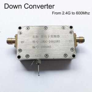
图传下变频器中国深圳供应商, 频率定制

名称: 图传下变频器
型号: LWDC-248258I
编号: 1805001
RF +12V IF
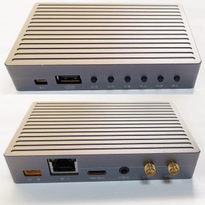
Name: Konwerter RF w dół
Model: LWDC-3000I
Model: LWDC-1400
Frequency input 2G~2.7G(2000~2700Mhz)
Lower: 1800Mhz
Frequency output: 200Mhz-700Mhz
SN2405002
| MIN | TYPE | MAKS | ||
| Pasmo częstotliwości roboczej (MHz) | 1300 | – | 1400 | 工作频段 (MHz) |
| Lokalny oscylator (MHz) | 1000 | 本振(MHz) | ||
| Częstotliwość pośrednia (MHz) | 300 | – | 400 | 中频(MHz) |
| Conversion gain Gain(dB) | 18 | 20 | 22 | 变频增益Gain(dB) |
| Zyskaj płaskość (dB) | ±1 | – | 增益平坦度(dB) | |
| Noise figure (dB) | 1.5 | – | 噪声系数(dB) | |
| Port Standing Wave Ratio VSWR | 1.5 | 1.8 | 2 | 端口驻波比VSWR |
| Port Impedance(om) | 50 | – | 端口阻抗(om) | |
| Maksymalna moc wejściowa (dBm) | -5 | 最大输入功率(dBm) | ||
| Maximum output power (dBm) | 15 | 最大输出功率(dBm) | ||
| Napięcie robocze (V) | 10 | 12 | 15 | 工作电压(V) |
| Prąd roboczy (mama) | 130 | 150 | 180 | 工作电流(mA) |
| Operating temperature (°C) | -25 | 55 | 工作温度(°C) | |
| Temperatura przechowywania (°C) | -45 | 65 | 存储温度(C) | |
| Dimension mm (without connectors) | 62x32x14mm | 尺寸 mm (不含连接器) |


Customize Frequency Specification Sheet Download
| Przedmiot | Parametr |
| częstotliwość wejściowa | 2100 MHz ~2500 MHz |
| częstotliwość wyjściowa | 350 MHz ~750 MHz |
| Częstotliwość lokalna | 1750 MHz |
| Liczba szumów | ≤1,5 dB |
| osiągać | 15 dB |
| Wyciek nośnika | ≤-20 dBm |
| Nierówność paska(8MHz) | ≤1,5 dB |
| IP3: | ≥15dBm |
| maksymalny poziom wejściowy | 0dBm |
| VSWR | ≤1,5 |
| temperatura pracy | -10~+60 ℃ |
| prąd napięciowy | ≤12 V/240 mA |
| Interfejs RF | N-50KFD |
| rozmiar | 108*48*22mm |
| Tryb zasilania | Zasilanie internetowe |


Paul –
This COFDM Digital Down Converter delivers flawless frequency conversion with ultra-low latency. The signal clarity and stability are unmatched—perfect for professional broadcast and surveillance applications. Gorąco polecam!