


sida loo cabbiro korontada gudbiyaha
Tusmada Tusmada
How to measure the transmitter power output to check the COFDM wireless video transmitters’ real power amplifier inside?
To transmit wireless video signals farther, the transmitter needs a powerful power amplifier.
So how do we measure the power amplifier of a wireless transmitter? In the above video, we have measured three times COFDM-908T, which was ordered from our customer. This client needs a 10-watt power amplifier for ground wireless video transmission. So we measure the transmitter TX power for him.
We have to use specialized instruments to test the RF output power of wireless video amplifiers.
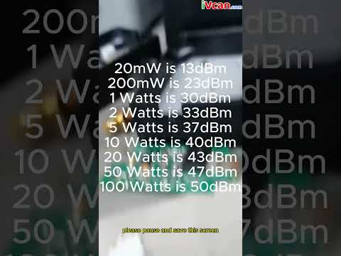
Marka hore, we need to know a table of output power and power amplifier power. Waa kuwan qaar ka mid ah waraaqaha u dhexeeya awoodda wax soo saarka iyo cabbirrada dBm ee uu soo bandhigay qalabku.
20mW waa 13dBm
200mW waa 23dBm
1 Watts waa 30dBm
2 Watts waa 33 dBm
5 Watts waa 37dBm
10 Watts waa 40 dBm
20 Watts waa 43dBm
50 Watts waa 47dBm
100 Watts waa 50dBm
The transmitters in the video all have built-in 10-watt power amplifiers, and the corresponding instrument should measure 40dBm.
Isla markaana, our equipment has a 40dBm attenuator added, so the instrument should show a performance of around 0dBm.
You can see the performance indicators in the video: one is 0 dBm, one is 0.07 dBm, and one is 0.18 dBm. From the table, we can see 0 dBm, They all have built-in 10-watt power amplifiers.
In the next video, we will demonstrate how to modify the output power through the parameter modification board.
We will show you how to change the wireless video transmitter from a 2-watt amplifier to a 1-watt one.
Please remember to follow our YouTube channel. If you have any suggestions for the COFDM wireless video transmitter and receiver, please feel free to communicate with us.
To measure the RF output power of a wireless video transmitter, you must use a power meter and a power sensor that are compatible with the transmitter’s signal format and modulation type.
To achieve proper power transfer, you must also match the impedance of the transmitter and the power sensor. Here are some procedures to follow:
- Turn on the power meter and connect the power sensor. Check that they are correctly calibrated and configured.
- Using a coaxial cable, connect the transmitter output to the power sensor input. To protect the power sensor from damage caused by high power levels, use an attenuation or a dummy load if possible.
- Set the transmitter’s frequency and modulation mode as desired. As needed, adjust the output power level.
- Pay attention to the power value displayed on the power meter. This is the transmitter’s RF output power in watts or decibels (dBm). If you have an oscilloscope, you may also use the peak-to-peak voltage formula to compute power.
- A directional coupler or a reflectometer is required to monitor the voltage standing wave ratio (VSWR), which indicates how well the transmitter and the power sensor are matched.
- These devices can calculate the VSWR by measuring both forward and reflected power. A low VSWR indicates a good impedance match and low power loss.
50-watt power amplifier at 175Mhz


50-watt power amplifier at 320Mhz


