


IP mesh xov tooj cua transceiver module rau drone yees duab txuas UHF Vcan2024
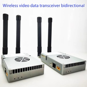
IP mesh radio transceiver module for drone video data link UHF
IP mesh radio transceiver module is suitable for point-to-multi-point or multi-point-to-multi-point network requirements.
Piv txwv, your project requires multiple transmitters and multiple receivers. Each node can act as a relay for other nodes. Each node cannot be individually defined as a transmitter, receiver, or repeater. Each node is a transmitter, a receiver, and a repeater. Such as security squads, bicycle racing, 2+ drones in the sky and 2+ receivers on the ground, thiab lwm cov ntaub ntawv.

Cov Txheej Txheem
Feature
- Two-way bidirectional transmission video data download and upload
- TDD OFDM full-duplex IP Mesh radio wireless transceiver module for video and data transmission
- Dual RF Power: 24±1dBm, 2-channel
- Optional Working Frequency: 566~678MHz (112Mhz range hopping), 1420~1530MHz (110Mhz range hopping)
- Three Ethernet RJ45 for video or data and One RS232 UART data link, control UART (TTL) chaw nres nkoj
- Support transmit distance: 500~2000 meters (av-rau-av), 5~22km (UAV-rau-av); For a longer range, we needed the extra power amplifier support. (2watts, 5watts, 10watts)
- This board supports the CX6779K modem.

FHSS Frequency Hopping
- We designed this wireless video and data transmission with uplink and downlink for those who need the frequency automatic hopping function.
- With frequency hopping technology (FHSS) to ensure better stable signal communication, when the current frequency signal is worse, the system will automatically change the working frequency to another frequency for a better signal.
- This bidirectional OFDM radio module can work from 566Mhz to 678MHz or from 1420Mhz to 1530MHz bandwidth. So the frequency range has 110Mhz bandwidth change or hopping. If you set the frequency bandwidth at 10 MHz, then there are 11 frequency points for hopping.
Specification
- TDD OFDM modulation (Need FDD COFDM model?)
- Kev txhawb 2 Frequency ranges (566~678MHz/1420~1530MHz)
- Supports FHSS frequency automatic hopping function
- 4/3/5/10/20/40MHz bandwidths
- Max 100Mbps throughput
- Dual RF transmission power: 24±1dBm, 2-channel for uplink and downlink
- Constellation: QPSK, 16Qam, 64Qam, yus tus kheej
- Cov Neeg Xiam Oob Khab: -95dbm (20MHz bandwidth)
- Supports IP Video Data Transmission (3 Chaw nres nkoj Ethernet)
- Cov kev them nyiaj yug serial cov ntaub ntawv transmission (1X RS232, 1XTL)
- Without extra PA, Up to 22km LOS (UAV-rau-av) thiab 2km POOB(av-rau-av)
- Can add 2watts, 5watts, los sis 10 watts to support longer range
- Web UI and control UART for management
- AES128 encryption
- Uplink thiab downlink kwj tswj (Video stream needs more and data streaming needs less)
- Networking hom: One-to-one P2P, one-to-many P2MP, many-to-one MP2P, relay/repeater, mesh or swarm network。
- Fais fab noj: <7W
- Qhov ntev: 80 x 57 x 9.1mm
- Yuag: 41g
- Working Temperate: -20°C + 65°C
- Storage Temperate: -40°C + 80°C
IP Radio Module Connector (input / Tso zis)
| Hwj huam nyob rau hauv lub hwj huam | 2PIN PH2.0mmConnector, DC hauv DC:9£30V |
| Ethernet-1 | 4PIN PH1.25m Connector |
| Ethernet-2 | 4PIN PH1.25m Connector |
| Ethernet-3 | 4PIN PH1.25m Connector |
| Cov ntaub ntawv UART | 3PIN PH1.25m Connector, RS232(or TTL 3.3V) |
| Tswj UART | 3PIN PH1.25m Connector, TTL 3.3V |
| USB | Micro USB Connector, rau software upgrading |
| Hloov | Tx/Rx tswj teeb liab rau sab nraum lub hwj huam amplifier |
| Main-Antenna | Tx/Rx Antenna chaw nres nkoj, IPEX |
| Ob-Antenna | Tx/Rx Antenna chaw nres nkoj, IPEX |
| 12V tawm | On-board 12V tawm(<200minyuam), txias ntxuam hwj huam mov |
Ethernet1, Ethernet2 and Ethernet3
The three Ethernet ports on board are bridged connections, so their IP addresses are the same. The photo below shows the 4PIN signals of the Ethernet port.

Switch Port
This port is a TX transmitter / RX receiver control signal for the extra power amplifier. The maximum RF transmission power of our module is 24±1dBm two channels, We also provide the correct power amplifier to increase the RF Power to 2-watt / 5-watt /10-watt if you need a longer range than 22km.
The below diagram shows how to add a power amplifier outside extra of this IP Radio Module.

This operation is for your reference only. If you need to add an external power amplifier, it is best to tell us and we will configure it for you, or ask a professional to operate it, txwv tsis pub, the PA will be easily burned.
| teeb liab | Electrical level | I/O | Hauj lwm lawm | mark |
| PA-enable1 | 1.8V | O | High electrical level: data transmitting, change to high electrical level at 3.19us before transmitting and to low electrical level at 0.26us after transmitting finished. | High-Tx
Low-Rx |
Cov ntaub ntawv UART
- The data UART is RS232 as default.
- We also can change the data port from RS232 to TTL 3.3V UART before the cargo delivery.
- The baud rate of data UART can be set as 115200, 57600, 38400, 19200, 9600, 4800, 2400, thiab 1200.

how the data UART works at the wireless transmission of the IP MESH radio Module
Control UART and USB port
Only one of these two ports is valid at the same time. Control UART is valid by default shipment. Please contact us if you need to use a USB UART. You can manage our module with Web UI or AT command via control UART.
LEDs light
LED1: Hwj huam COJ, Liab, teeb rau tej powered.
LED2: blue, LED3: Ntsuab, LED2 and LED3 indicate the wireless working status as described in the below table.
| Central node | Blue LED2 light on all the time and green LED3 is not light |
| Access node | Green LED3 light on all the time when the access node is connected with the central node. |
| The blue LED2 indicate the access node linking signal status with the central node.
When the wireless linking signal is strong, blue LED2 blinks every 30 vib nas this; When the wireless linking signal is middle, blue LED2 blinks every 6 vib nas this; When the wireless linking signal is weak, blue LED2 blinks every 1 Fiab. |
Sometimes customers may need to assemble the indicating LEDs on their housing case panel, so our board also provides a soldering hole for the three LED signals. The LED signal is described in the below table.
| LED | Hauj lwm lawm | Representation soldering hole |
| LED1 | Hwj huam COJ | LED1-GND and LEDs-VCC |
| LED2 | Wireless indicating LED | LED2-GND and LEDs-VCC |
| LED3 | LED3-GND and LEDs-VCC |
Wireless networking with the IP MESH Radio Module
- Our module supports two operating modes: Access Node thiab Central Node. It can be managed through Web UI or AT command via control UART.
- Our module supports features of a maximum of 63 Access Nodes txuas nrog ib Central Node. All the Nodes are in the same wireless LAN and share the whole transmission bandwidth (maximum 100Mbps throughout).
- Data from the Central Node to the Access Node, Peb hu downlink, and data from the Access Node to the Central Node, Peb hu uplink.
- Uplink thiab downlink kwj piv tau los ntawm web UI los yog AT command.
- When using Our module for Point-to-Point transmitting, uplink thiab downlink muab cov tseem transmission bandwidth (maximum 100Mbps throughout) ib yam nkaus thiab.
- Our module supports networking modes: Taw tes-rau-taw tes, Point-to-Multi-point, relay, thiab Mesh (specify mesh version when ordering).

MESH Centerless Networking


Yog tus thawj saib xyuas"IP mesh xov tooj cua transceiver module rau drone yees duab txuas UHF Vcan2024”
Yam khoom


Unidirectional ib-txoj kev
Mini Size HDMI Encoder Board dua IP Ethernet RJ45 Tso zis modulator H.265 HTTP RSTP UDP ONVIF TCP

TX RX Module
FPV Analog video Transmitter CVBS audio yees duab module sender 400-900MHz UHF vcan1904


Kev
Muaj cov tsis muaj kev kaj.