


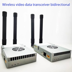
UAV Sendrata Video Datumoj RC Ligo por Virabelo 15-20-30-50-100-150km 1.4G / 2.4G / 5.8G-ricevilo dissendilo-ricevilo Vcan1818
UAV Sendrata Video Datumoj RC Ligo por Virabelo 15-20-30-50-100-150km 1.4G / 2.4G / 5.8G-ricevilo dissendilo-ricevilo Vcan1818


Enhavtabelo
trajto:
- Kontrolo de Video Datumoj 3 en 1
- 30-60KM sendrata transdono ( 2.4G frekvenco, 2Ok: 30km; 5Ok: 50km; 10Ok: 100km)
- 4K altdifinaj bildoj kun malalta latenco
- H265/H264 videokunpremo
- Riĉa interfaco (Ethernet por IP-fotilo, potenco, SBUS, TTL, adaptitajn)
- Adapta retranssendo
- Aŭtomata frekvenca saltado
specifo:
kanalo bandwidth: 2.5MHz(suprenligo), 10MHz(malsuprenligo)
Maksimuma ellasa energio: 27dBm / 30dBm
video formato:
DE: PAL, 50INTSC, 60i
HDMI: 576i60, 480p@60fps, 720p@50fps, 720p@60fps, 1080p@50fps, 1080p@60fps
SDl: 720p@50fps, 720p@60fps, 1080p@50fps, 1080p@60fps
modulado metodo: OFDM
konstelacio: BPSK, QPSK, 16QAM
Plusendu erarkorektan kodon: LDPC(1/2, 2/3, 3/4, 5/6)
Dupleksa reĝimo: TDD
Malsuprenliga traflua indico: 2Mbps~8Mbps
Suprenliga trairo-indico: 300kbps (seria haveno + rethaveno + fora kontrolo)
Video-interfaco: rethaveno, HDMI/SDI/AV
Aliaj interfacoj: seria haveno, PPM/SBUS, SB
ĉifrado: AES128/256
Video Kunpremo: H.264/H265(HDMI/SDI/AV)
Ekran-al-ekrana latenco: <300m
Grunda fina grandeco:
92X69X24mm (rethaveno)
Aera unuograndeco:
92X69X24mm
pezo: 195g (Vcan1818-2W-30km, 195gramo)
laboranta temperaturon: -20°C-55 °C

Eniro / eligo

- MIMO-konektilo: potenco, Ethernet haveno, Seria haveno de transdono de datumoj, kaj teleregilo SBUS/TTL/PPM
- USB: Konekti al la komputilo USB, kiu povas esti uzata por agordi kaj ĝisdatigi la aparaton kaj aliajn rilatajn operaciojn.

LED
De maldekstre dekstren estas:
Potenca indikila lumo (1)
Eterretaj havenaj indikiloj (3)
Supren kaj malsuprenliga indikiloj (2).
Kiam la sendrata ligo estas establita normale, la ligindikilo de la aersistemo estos malŝaltita. La malsuprenliga indikilo estas multipleksita kun la deviga indikila funkcio.
Butono de paro
Longe premu la butonon ĝis la deviga indikila lumo ekbrilas, poste liberigu ĝin por plenumi la ligan operacion. La fabrika ekipaĵo estis ligita. Se ĝi ne estas necesa, la kliento ne bezonas ligi denove.
Aera Unuo

| neniu. | interfaco |
| 1,2,3 | Ethernet |
| 4,5 | S.BUS, kiel montrite en la bildo, la 1st stifto de la maldekstro de la Dupont-konektilo estas la S.BUS-signalo, kaj la 3rd estas G. |
| 6,7 | Telemetria serialo, kiel montrite en bildo, la 2nd pinglo de maldekstre de GH1.25-konektilo estas Rx, la 3rd estas Tx, la 6th estas G. (TTL defaŭlte, RS232/422 alternativo) |
| 8 | PPM, kiel montrite en la bildo, la 1st pinglo de maldekstre estas la PPM-signalo, kaj la 3rd estas G. |
| 9 | potenco |
Ethernet 1, Ethernet 2
TTL 1 spuristo, TTL2
SBUS 1, SBUS 2
potenco En
Tera Unuo

| neniu. | interfaco |
| 1,2,3 | Ethernet |
| 4,5 | S.BUS, kiel montrite en bildo, la 1st pinglo de maldekstre estas S.BUS-signalo, la 2nd estas 5V+, la 3rd estas G. |
| 6,7 | Seria-USB(TTL-USB defaŭlte, RS232/422 alternativo) |
| 8 | PPM |
| 9 | potenco |
Ethernet 1, laŭvola distanca grado
TTL1, TTL2
SBUS 1, SBUS 2
potenco En
Oftaj Demandoj
- La ofteco estas 2410-2478 Mhz en nia prova video.
- This model's working frequency is customized, ni ankaŭ povas ŝanĝi ĝin al 2325 Mhz.
- Vcan1818-5W has 6Mbps at 20km, 30km, kaj 40 km.
- Vcan1818-2W has 6Mbps at 20km, and 2-3Mbps at 30 kaj 40 km.
- La defaŭlta frekvenca gamo estas 800-900Mhz
- Krom 800 MHz, 1.4G kaj 2.4G, Aliaj frekvencoj povas esti personecigitaj se la menda kvanto renkontas nian MOQ-peton (50 paroj)
- La defaŭlta dissendilo havas 2 aroj de RJ45 Ethernet Vidkamera enigo.
- Ni ankaŭ povas personecigi 3 aroj de RJ45 Ethernet-vidkamera enigo kiam vi mendas kaj sciigas nin.
- Potenco Amplifilo ĉe 0.5 Vatoj subtenas 2.4G kaj 5.8G ambaŭ.
- Potenco Amplifilo ĉe 10 vatoj subtenas 2.4G aŭ 5.8G, ĝi ne povas subteni du frekvencbendojn ĉe tio 10 Eligo de vatoj.
- If you choose a 10-watt power amplifier inside, it can not support 2.4G and 5.8G at the same time.
- jes, 3G~3.9Ghz working frequency is optional. Fakte, we can modify other frequencies if you need. You should have an order and agree to wait for 2 months for engineer development. (need re-layout the PCBA and small quantity to produce and test)
- Regarding automatic frequency hopping-FHSS, jes, it will auto-change to use the next working frequency if the signal is blocked or jammed.
- The drone wireless video data link module Vcan1818 power supply range: DC 18-26V.
- The antenna must be installed before powering on.
- Ankaŭ, you should double check that the screws of the antenna and RF transmitter are tightened.
- Because if the antenna is not installed or the contact is poor, the power amplifier will burn out.
- You should install both two antennas on the air terminal.
- It is best to use the transmitter antenna we configure for you, ensuring that the frequency and gain of the antenna are tested and verified.
- The two antennas are best installed on both sides of the drone to ensure that the drone can still get the best signal when turning and maintain uninterrupted contact with the ground control station.
- You should install both two antennas on the ground terminal.
- It is best to use the transmitter antenna we configure for you, ensuring that the frequency and gain of the antenna are tested and verified.
-
The two ground wireless video data receiver antennas should be kept as far apart as possible.
-
They should be installed as high as possible above the ground to receive the signal from the drone transmitter.
-
The feeder cable is relatively long. For the convenience of packaging and transportation, it is bundled into a circle. En efektiva uzo, you must remember to unfold the feeder line. Do not let it remain in its original round shape, because this will invisibly create an electronic interference environment.
-
jes, just output the standard PPM signal through the trainer port;
-
Or use the S.BUS receiver for communication.
- neniu, a plane can only have one air unit transmitter. If you need it to support more cameras, please tell us to offer you a better solution.
- P2P point-to-point devices can only install one ground terminal.
- P2MP point-to-multipoint devices support multiple ground terminals.
- If you have this requirement, please remember to tell us when placing your order and we can configure it for you.
- Please check whether the antenna of the drone VTX is far away from the GPS to avoid blocking interference from the GPS.
- The frequency band of 1.4G equipment is close to the GPS frequency band, so a certain degree of antenna isolation must be ensured.
- LED1 (power indicator light): After the power is turned on, the light is always blue.
- LED2~4 (network connection indicators):
- If the light is always on, it means that the physical link of the network port is connected.
- If the light is off, it means that the physical link of the network port is not connected.
- LED5 (uplink indicator):
- Kiam la lumo estas ŝaltita, it indicates that the link between the ground unit and the air unit has been established;
- When the light is off, it indicates that the link between the ground unit and the air unit has been disconnected.
- LED6 (downlink indicator light):
- Kiam la lumo estas ŝaltita, it indicates that the link between the air unit and the ground unit has been established;
- When the light is off, it indicates that the link between the air unit and the ground unit has been disconnected.
Please follow the steps below:
- Please check whether the power supply of the air end and ground end modules is normal;
- Please check whether the air end and the ground end are successfully bound;
- Please check whether the antenna installation of the air terminal and the ground terminal module is normal: whether there is any obstruction in the installation position of the antenna; whether the antenna interface is loose; whether the feeder is not tightened, and whether the interface is loose;
- Use the management software to check whether the transmitting frequency of the ground terminal is consistent with the receiving frequency of the air terminal;
- If none of the above operations can solve the problem, please contact our wireless video link technical support person.
Please follow the steps below:
- Please check whether the power supply of the air end and ground end modules is normal;
- Please check whether the air end and the ground end are successfully bound;
- Please check whether the antenna installation of the air terminal and the ground terminal module is normal: whether there is any obstruction in the installation position of the antenna; whether the antenna interface is loose; whether the feeder is not tightened, and whether the interface is loose;
- Use the management software to check whether the transmitting frequency of the air terminal is consistent with the receiving frequency of the ground terminal;
- If none of the above operations can solve the problem, please contact our wireless video link technical support person.
Please follow the steps below:
-
Please check whether the power supply of the air end and ground end modules is normal, and whether the modules start normally;
-
Please check whether the network cable is connected normally;
-
Please check whether the network camera is powered normally;
-
If none of the above operations can solve the problem, please contact our wireless video link technical support person.
Please follow the steps below:
-
Confirm whether the wireless link status is established normally;
-
Please check whether the connection between the flight controller and the air terminal is correct, and whether the connection between the ground terminal and the ground station is correct;
-
Please check whether the data transmission line sequence of the air end and ground end modules is normal. Our company provides standard cables. If you do the wiring yourself, please check the line sequence;
-
Check whether the data transmission baud rate is consistent with the flight control through the management software;
-
Whether the computer firewall of the ground station is closed;
-
If none of the above operations can solve the problem, please contact our wireless video link technical support person.
Please follow the steps below:
-
Confirm whether the wireless link status is established normally.
-
Please check whether the connection between the flight controller and the air terminal is correct, and whether the connection between the ground terminal and the remote control is correct;
-
If using PPM mode, please check the mode configuration of the remote control; if using S.BUS mode, please check the receiver and remote control configuration;
-
Please check whether the remote control line sequence of the air end and ground end modules is correct;
-
Check whether the remote control mode is configured correctly through the management software;
-
If none of the above operations can solve the problem, please contact our wireless video link technical support person.
Please follow the steps below:
-
Confirm whether the wireless link status is established normally;
-
Confirm whether the network physical connection indicators of the air terminal and the ground terminal are normal;
-
If using a network camera, please confirm the IP address of the network camera, login user name and password;
-
Whether the IP address configuration of the ground station computer and the network camera are in the same network segment;
-
Whether the video stream address configuration for playing RTSP is correct;
-
Whether the computer firewall of the ground station is closed;
-
If none of the above operations can solve the problem, please contact our wireless video link technical support person.
Please follow the steps below:
-
Confirm whether the downlink mode configuration is reasonable;
-
Whether the network cable used is connected properly;
-
Whether there is interference in the downlink, consider changing the working frequency point;
-
If there is no interference, whether the limit distance of the communication link has been reached;
-
Observe whether the downlink rate of the pod fluctuates too much. Ekzemple, the fixed bit rate of the pod is 3 Mbps, and the downlink rate of the client is set to 3.97 Mbps, and the peak value of the pod’s bit rate is likely to be at a certain stage If it exceeds 3.97 Mbps, there will be lag or mosaic phenomenon at this time. Set the downlink rate of the client to 5.27 Mbps, and verify whether the downlink rate exceeds 3.97 Mbps. If it exceeds 3.97 Mbps, set the downlink rate of the client to be greater than the peak value of the pod;
-
Check the real-time downlink rate of the client, whether there are double camera streams;
-
If none of the above operations can solve the problem, please contact our wireless video link technical support person.
Please follow the steps below:
-
Confirm whether the antenna and connecting cable are installed correctly and whether they are standard materials of wireless video link;
-
Ensure that the antenna installation of the air terminal will not be blocked by the load, and that there is no obvious obstruction in the short distance of the antenna of the ground terminal, and that the antenna of the air terminal and the ground terminal are perpendicular to the ground;
-
Check whether the video transmission equipment hardware such as the power amplifier is damaged;
-
Whether the downlink mode configuration value is unreasonable, and the high-speed downlink mode will significantly reduce the communication distance;
-
Whether the working frequency is significantly interfered, you can select the optimal frequency through the client;
-
Whether the air terminal and the ground terminal are seriously blocked in the flight environment, and the complex geographical environment will affect the communication distance;
-
If none of the above operations can solve the problem, please contact our wireless video link technical support person.
-
Pardonon, the most used working frequency is 800Mhz, 1.4G, kaj 2.4G. Other frequencies should be customized.
- 443Mhz seems COFDM frequency range from 170-860Mhz, but most COFDM video transmitters and receivers are one-way transmission.
The two-way transmission model is here.
Uzanto Manlibro
rilataj produktoj


video Dissendilo
2300Mhz 2.4G Long Range UAV Video Datuma Transdono Sistemo Por Drone VTOL Multicopter